FRONT FINAL DRIVE ASSEMBLY
FRONT FINAL DRIVE: F160A
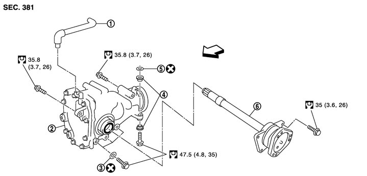
Exploded View
|
1. |
Air breather hose |
2. |
Front final drive assembly |
3. |
Washer with electric corrosion preventive material |
|
4. |
Bushing |
5. |
Washer with electric corrosion preventive material |
6. |
Side shaft |
 : Vehicle front : Vehicle front |
|||||
|
Refer to Components for the symbols shown in the figure. |
|||||
Removal and Installation
 REMOVAL
- 1.Remove the engine assembly with the suspension member from the vehicle. Refer to Exploded View (GT-R certified NISSAN dealer).
- 2.Remove the engine assembly from the suspension member. Refer to Exploded View.
- 3.Remove the front drive shaft (LH and RH). Refer to Exploded View (GT-R certified NISSAN dealer).
- 4.Remove the side shaft mounting bolts, and remove the side shaft by tapping with plastic hammer.
■ CAUTION ■
The engine oil pan (upper) uses heat-resistant magnesium. Never apply an impact to it. - 5.Remove the alternator. Refer to Exploded View (GT-R certified NISSAN dealer).
- 6.Remove the air breather hose.
- 7.Remove the oil return tube (bank 1). Refer to Exploded View.
- 8.Remove the engine mount bracket (RH) (lower). Refer to Exploded View (GT-R certified NISSAN dealer).
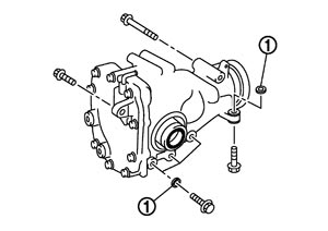
- 9.Remove the front final drive assembly mounting bolts with the washer with electric corrosion preventive material (1).
■ CAUTION ■
Never damage the oil pressure switch connector. - 10.Remove the front final drive assembly from the engine assembly.
- 11.Remove the bushings from the front final drive assembly.
INSTALLATIONNote the following, and install in the reverse order of removal.
- Apply multi-purpose grease to the side oil seal and side shaft when installing the side shaft.
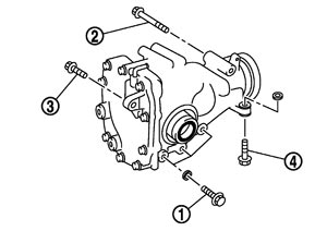
- When installing the front final drive assembly, temporarily tighten the bolt and finally tighten the bolt as per the following order: gear carrier side (1), gear carrier upper (2), carrier cover (3), and gear carrier lower (4).
 ■ CAUTION ■
- When installing, align the joint surface between the gear carrier and the oil pan.
- The engine oil pan (upper) uses heat-resistant magnesium. Never apply an impact to it.
- Always install the washer with electric corrosion preventive material.
- Never reuse the washer with electric corrosion preventive material.
- When installing, align the joint surface between the gear carrier and the oil pan.
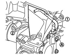
- Install the air breather hose (1) as shown in the figure.
 ■ CAUTION ■
- Make sure there are no pinched or restricted areas on the breather hose caused by bending or winding when installing it.
- Position the paint mark (A) on the air breather hose toward the right side of the vehicle.
- The vehicle side of the air breather hose must be positioned at the engine mount bracket (RH) (2).
- Be sure to insert air breather hose to breather connector until hose end reaches the tube bend R portion.
- Make sure there are no pinched or restricted areas on the breather hose caused by bending or winding when installing it.
- When oil leaks while removing final drive assembly, check oil level after the installation. Refer to Inspection.