DAYTIME RUNNING LIGHT SYSTEM
XENON TYPE
System Diagram
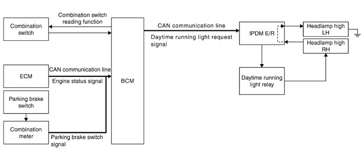
System Description
 OUTLINE
- Turns the headlamp high ON (high beam at approximately half illumination) as the daytime running light.
- Daytime running light is controlled by daytime running light control function and combination switch reading function of BCM, and relay control function of IPDM E/R.
DAYTIME RUNNING LIGHT OPERATION - BCM detects the combination switch condition by the combination switch reading function.
- BCM detects the engine condition by the engine status signal received from ECM with CAN communication.
- BCM detects the parking brake condition by the parking brake switch signal received from combination meter with CAN communication.
- BCM transmits the daytime running light request signal to IPDM E/R with CAN communication according to the daytime running light ON condition.
- Engine running
- Lighting switch OFF or 1ST
- Parking brake switch OFF
- Ignition switch ON
- IPDM E/R controls the daytime running light relay (ground-side) to turn ON according to the daytime running light request signal.
- Power is supplied from the daytime running light relay through headlamp high (RH) and IPDM E/R to headlamp high (LH). And high beam headlamps are illuminated (approximately half illumination) as the daytime running light.
Daytime running light ON condition
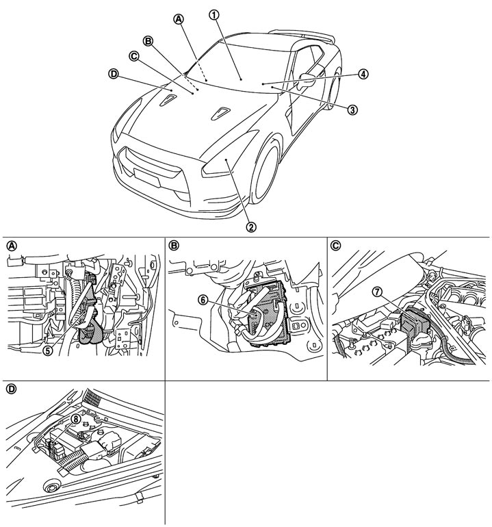
Component Parts Location
|
1. |
Parking brake switch |
2. |
Daytime running light (Headlamp HI) |
3. |
Combination switch |
|
4. |
Combination meter |
5. |
ECM |
6. |
BCM |
|
7. |
IPDM E/R |
8. |
Daytime running light relay |
|
|
|
A. |
Over the glove box |
B. |
Dash side lower (passenger side) |
C. |
Engine room dash panel (RH) |
|
D. |
Engine room dash panel (RH) |
|
|
|
|
Component Description
|
Part |
Description |
|
|
BCM |
|
|
|
IPDM E/R |
Controls the relay and supplies voltage to the load according to the request from BCM (with CAN communication). |
|
|
Daytime running light relay |
Switches headlamp (HI) circuit to illuminate the daytime running light. |
|
|
Combination switch (Lighting & turn signal switch) |
Refer to System Diagram. |
|
|
ECM |
Transmits the engine status signal to BCM (with CAN communication). |
|
|
Combination meter |
Transmits the parking brake switch signal to BCM (with CAN communication). |
|