REAR WHEEL HUB AND HOUSING
Exploded View
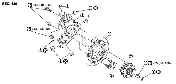
|
1. |
Ball seat |
2. |
Axle housing |
3. |
Bushing |
|
4. |
Cotter pin |
5. |
Back plate |
6. |
Anchor block |
|
7. |
Wheel hub and bearing assembly |
8. |
Wheel hub lock nut |
|
|
|
Refer to Components for the symbols in the figure. |
|||||
Removal and Installation
 REMOVAL
- 1.Remove tire with power tool.
- 2.Remove brake hose bracket. Refer to Exploded View.
- 3.Remove caliper assembly. Hang caliper assembly in a place where it will not interfere with work. Refer to Exploded View (GT-R certified NISSAN dealer).
- 4.Remove disc rotor. Refer to Removal and Installation (GT-R certified NISSAN dealer).
- 5.Remove cotter pin, then loosen wheel hub lock nut with a power tool.
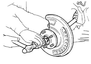
- 6.Patch wheel hub lock nut with a piece of wood. Hammer the wood to disengage wheel hub and bearing assembly from drive shaft.
- Never place drive shaft joint at an extreme angle. Also be careful not to overextend slide joint.
- Never allow drive shaft to hang down without support for counterpart such as joint sub-assembly, and the other parts.
■ CAUTION ■
NOTE:
Use a suitable puller, if wheel hub and bearing assembly and drive shaft cannot be separated even after performing the above procedure.- 7.Remove wheel hub lock nut.
- 8.Remove parking brake shoe and parking brake cable from back plate. Refer to Exploded View, Exploded View (GT-R certified NISSAN dealer).
- 9.Remove stabilizer connecting rod (upper side). Refer to Exploded View.
- 10.Set suitable jack under axle housing.
- 11.Remove cotter pin of suspension arm, and then loosen mounting nut.
- 12.Separate shock absorber from axle housing with power tool. Refer to Exploded View.
- 13.Separate suspension arm from axle housing so as not to damage ball joint boot using ball joint remover.
- Temporarily tighten nuts to prevent damage to threads and to prevent the ball joint remover from coming off.
- Never place drive shaft joint at an extreme angle. Also be careful not to overextend slide joint.
- Never allow drive shaft to hang down without support for counterpart such as joint sub-assembly, and other parts.
■ CAUTION ■
- 14.Separate front lower link from axle housing. Refer to Exploded View.
- 15.Separate rear lower link from axle housing. Refer to Exploded View.
- 16.Separate radius rod from axle housing. Refer to Exploded View.
- 17.Remove wheel hub and bearing assembly.
- 18.Remove anchor block mounting nuts, and then remove anchor block and back plate from axle housing.
INSTALLATIONNote the following, and install in the reverse order of removal.
- When assembling the shaft, never press it, but pull it until fully seated by tightening the wheel hub lock nut.
- Check that anticorrosive oil is applied to the thread of the drive shaft. If not, apply appropriate oil such as engine oil.
- If sufficient oil is not applied to the thread of the drive shaft, the wheel hub lock nut may be seized and the tightening torque reaches the specified limit prematurely. It may cause looseness or abnormal noises.
- Perform the final tightening of each of parts under unladen conditions, which were removed when removing wheel hub and bearing assembly and axle housing.
- Never reuse cotter pin, ball seal and bushing.
Inspection
INSPECTION AFTER REMOVAL Wheel Hub and Bearing Assembly
Check the wheel hub and bearing assembly for wear, cracks, and damage. Replace if necessary.
Axle HousingCheck the axle housing for wear, cracks, and damage. Replace if necessary.
Ball Joint InspectionCheck for boot breakage, axial looseness, and torque of suspension arm ball joint. Refer to Inspection (GT-R certified NISSAN dealer).
INSPECTION AFTER INSTALLATION- 1.Adjust parking brake operation (stroke). Refer to Inspection and Adjustment.
- 2.Check wheel alignment. Refer to Inspection.
- 3.Adjust neutral position of steering angle sensor. Refer to Special Repair Requirement (GT-R certified NISSAN dealer).