REAR DRIVE SHAFT
Exploded View
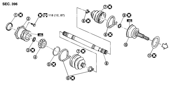
|
1. |
Plug |
2. |
Housing |
3. |
Snap ring |
|
4. |
Ball cage/steel ball/inner race assembly |
5. |
Stopper ring |
6. |
Boot band |
|
7. |
Boot |
8. |
Shaft |
9. |
Circular clip |
|
10. |
Joint sub-assembly |
11. |
Dust shield |
|
|
 : Wheel side : Wheel side |
|
|
|
|
|
 : NISSAN genuine grease or an equivalent. : NISSAN genuine grease or an equivalent. |
|||||
|
Refer to Components for symbols not described on the above. |
|||||
Removal and Installation
 REMOVAL
- 1.Remove axle housing. Refer to Exploded View.
- 2.Remove mounting bolts between side flange and drive shaft.
INSTALLATIONNote the following, and install in the reverse order of removal.
- When assembling the shaft, never press it, but pull it until fully seated by tightening the wheel hub lock nut.
- Check that anticorrosive oil is applied to the thread of the drive shaft. If not, apply appropriate oil such as engine oil.
- If sufficient oil is not applied to the thread of the drive shaft, the wheel hub lock nut may be seized and the tightening torque reaches the specified limit prematurely. It may cause looseness or abnormal noises.
- Perform the final tightening of each of parts under unladen conditions, which were removed when removing wheel hub and bearing assembly and axle housing.
- Never reuse cotter pin, ball seal and bushing.
Inspection
INSPECTION AFTER REMOVAL- Move joint up/down, left/right, and in the axial direction. Check for motion that is not smooth and for significant looseness.
- Check boot for cracks, damage and grease leakage.
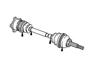
- Disassemble drive shaft and exchange malfunctioning part if there is abnormal condition.
INSPECTION AFTER DISASSEMBLY Shaft
ShaftCheck shaft for runout, cracks and other damage. Replace it if necessary.
Joint-Sub Assembly (Wheel Side)Check the following items, replace the parts if necessary.
- Joint sub-assembly for rough rotation or excessive axial looseness.
- The inside of the joint sub-assembly for entry of foreign material.
- Joint sub-assembly for compression scars, cracks or fractures inside of joint sub-assembly.
Housing and Ball Cage/Steel Ball/Inner Race AssemblyReplace housing and ball cage/steel ball/inner race assembly if there is scratching or wear of housing roller contact surface or spider roller contact surface.
NOTE:
Housing and ball cage/steel ball/inner race assembly are used in a set. INSPECTION AFTER INSTALLATION- 1.Adjust parking brake operation (stroke). Refer to Inspection and Adjustment.
- 2.Check wheel alignment. Refer to Adjustment.
- 3.Adjust neutral position of steering angle sensor. Refer to Special Repair Requirement (GT-R certified NISSAN dealer).