POWER STEERING CONTROL UNIT
EPS
Reference Value
 TERMINAL LAYOUT
 PHYSICAL VALUES
|
Terminal No. (Wire color) |
Description |
Condition |
Value (Approx.) |
|||
|
+ |
- |
Signal name |
Input/Output |
|||
|
1 (LG) |
Ground |
Power steering solenoid valve voltage |
Output |
Vehicle speed: 0 km/h (0 MPH) (Engine is running) |
4.4 – 6.6 V |
|
|
Vehicle speed: 100 km/h (62 MPH) |
2.4 – 3.6 V |
|||||
|
3 (G) |
Ground |
Ignition switch power supply |
Input |
Ignition switch: ON |
Battery voltage |
|
|
Ignition switch: OFF |
0 V |
|||||
|
5 (B) |
Ground |
Power steering solenoid valve ground |
— |
Always |
0 V |
|
|
6 (B) |
Ground |
Ground |
— |
Always |
0 V |
|
|
8 (L) |
Ground |
Vehicle speed signal |
Input |
Vehicle speed: 40 km/h (25 MPH) ■ CAUTION ■ Check air pressure of tire under standard condition. |
NOTE:
The maximum voltage varies depending on the specification (destination unit).
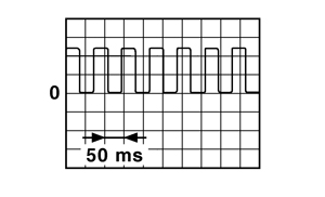
|
|
|
10 (SB) |
Ground |
Engine speed signal |
Input |
Engine is running
|
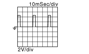
|
|
Engine is running
|
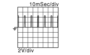
|
|||||
Wiring Diagram - ELECTRONICALLY CONTROLLED POWER STEERING SYSTEM -
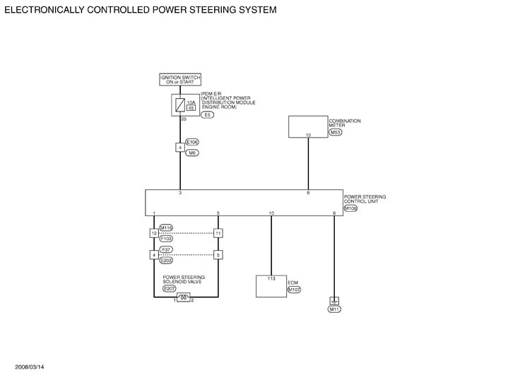
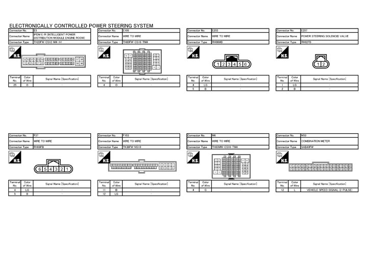
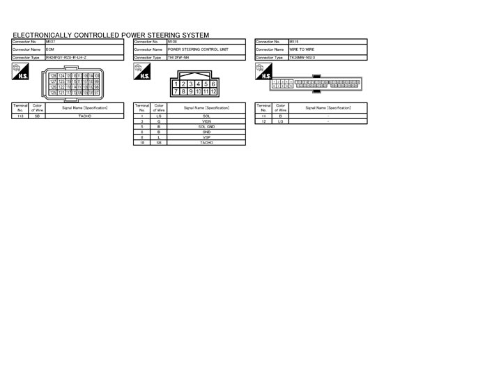
Fail-Safe
EPS system- EPS system enters the fail-safe mode (that allows the steering force to be controlled without impairing the drivability) if any of the input/output values to/from EPS system (power steering control unit) deviate from the standard range.
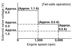 NOTE:The system enters the fail-safe mode if the engine speed remains at 1,500 rpm or more for over 10 seconds while the vehicle is stopped. This is normal.
 - The fail-safe function is canceled when a vehicle speed signal of 2 km/h (1.2 MPH) or more is inputted or the ignition switch is turned OFF→ON. EPS system restores the normal operation at that time.
|
Mode |
Warning lamp |
DTC |
Detection point (malfunction part) |
Error area and root cause |
|
|
Fail-safe |
— |
— |
Vehicle speed signal input |
|
|