STEERING COLUMN
Exploded View
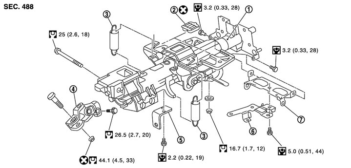
|
1. |
Steering column assembly |
2. |
Slide plate |
3. |
Spring |
|
4. |
Upper joint |
5. |
Bracket |
6. |
Bracket |
|
7. |
Bracket |
|
|
|
|
|
Refer to Components for symbols in the figure. |
|||||
Removal and Installation
 REMOVAL
- 1.Set the vehicle to the straight-ahead position.
- 2.Place the tilt to the highest level. Place the telescopic to the longest level.
- 3.Remove driver air bag module. Refer to Exploded View.
- 4.Remove steering wheel. Refer to Exploded View.
- 5.Remove the steering column cover. Refer to Exploded View.
- 6.Remove spiral cable. Refer to Exploded View.
- 7.Remove combination switch. Refer to Exploded View.
- 8.Remove the instrument driver lower panel. Refer to Exploded View.
- 9.Remove combination meter. Refer to Exploded View.
- 10.Disconnect each switch harness connectors installed to steering column assembly.
- 11.Remove the upper joint mounting bolt and nut (lower shaft side), and separate the joint from lower shaft.
- 12.Remove steering column assembly.
- Never give axial impact to steering column assembly during removal.
- Never move steering gear assembly when removing steering column assembly.
■ CAUTION ■
INSTALLATIONNote the following, and install in the reverse order of removal.
- When installing the slide plate (1), contact it with the protrusion (C) of steering column, mating the half round cut (A) of slide plate with the protrusion (B) of steering column.
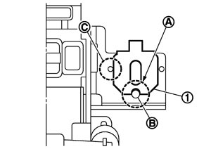
- Be careful of the following points when installing the steering column assembly.■ CAUTION ■
- Never give axial impact to steering column assembly during installation.
- Never move steering gear assembly.
- Never reuse the joint mounting nut (lower shaft side).
- Never reuse the slide plate.
- Never give axial impact to steering column assembly during installation.
- Adjust neutral position of steering angle sensor. Refer to Special Repair Requirement (GT-R certified NISSAN dealer).
Inspection
INSPECTION AFTER REMOVAL- Check each part of steering column assembly for damage or other malfunctions. Replace if necessary.
- Measure steering column assembly rotating torque using a preload gauge [SST: ST3127S000 (J-25765-A)]. Replace steering column assembly if outside the standard.
Standard Rotating torque : Refer to Steering Column Operating Range (GT-R certified NISSAN dealer). - Install the bracket and steering column housing so that the clearance (A) is within the specified range as described below. Replace steering column assembly if out side the standard.
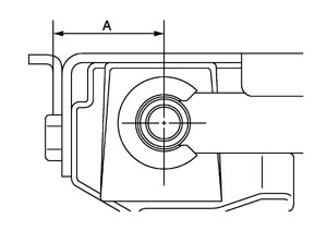
Standard A : Refer to Steering Column Mounting Dimensions (GT-R certified NISSAN dealer).
INSPECTION AFTER INSTALLATION- Check each part of steering column assembly for damage or other malfunctions. Replace if necessary.
- Check the steering wheel play, neutral position steering wheel, steering wheel turning force, and front wheel turning angle. Refer to Inspection.
- Check tilt and telescopic mechanism operating range tilt operating range (L1), telescopic operating range (L2) as shown in the figure.
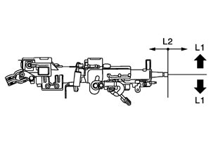
Standard L1 : Refer to Steering Column Operating Range (GT-R certified NISSAN dealer). L2 : Refer to Steering Column Operating Range (GT-R certified NISSAN dealer).