STEERING GEAR AND LINKAGE
Exploded View
 REMOVAL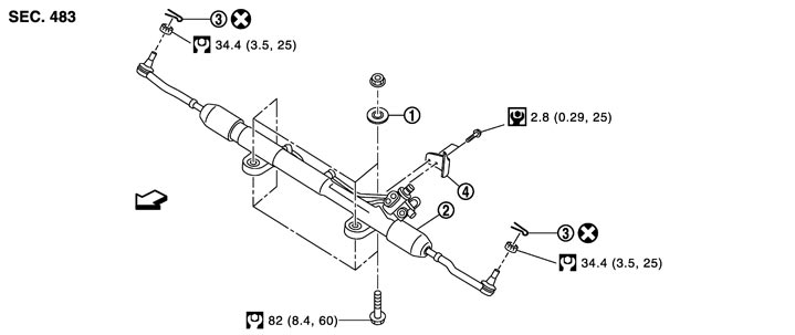
|
1. |
Spacer |
2. |
Steering gear assembly |
3. |
Cotter pin |
|
4. |
Heat insulator |
|
|
|
|
 : Vehicle front : Vehicle front |
|||||
|
Refer to Components for symbols in the figure. |
|||||
DISASSEMBLY 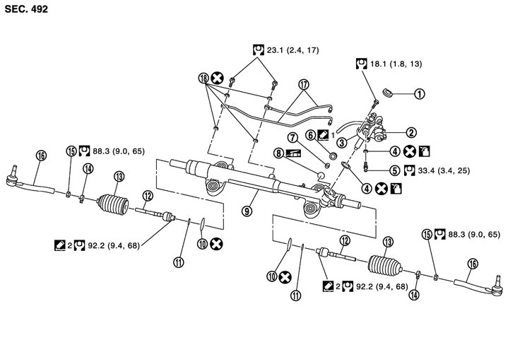
|
1. |
Rear cover cap |
2. |
Power steering solenoid valve |
3. |
Gear-sub assembly |
|
4. |
O-ring |
5. |
Low pressure piping |
6. |
Adjusting screw |
|
7. |
Spring |
8. |
Retainer |
9. |
Gear housing assembly |
|
10. |
Boot clamp (stainless wire) |
11. |
Spacer |
12. |
Inner socket |
|
13. |
Boot |
14. |
Boot clamp |
15. |
Outer socket lock nut |
|
16. |
Outer socket |
17. |
Cylinder tubes |
18. |
Copper washer |
 : Apply power steering fluid. : Apply power steering fluid. |
|||||
 1: Apply Genuine High Performance Thread Sealant or equivalent. Refer to Recommended Chemical Products and Sealants.
 |
|||||
|
2:Apply Genuine Medium Strength Thread Locking Sealant or equivalent. Refer to Recommended Chemical Products and Sealants |
|||||
 : Apply multi-purpose grease. : Apply multi-purpose grease. |
|||||
|
Refer to Components for symbols not described on the above. |
|||||
Removal and Installation
REMOVAL- 1.Set the vehicle to the straight-ahead position.
- 2.Remove tires with a power tool.
- 3.Remove engine floor under cover and front under cover. Refer to Exploded View, Exploded View.
- 4.Remove cotter pin (1), and then loosen the nut.
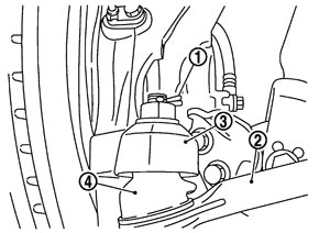
- 5.Remove steering outer socket (2) from steering knuckle (3) so as not to damage ball joint boot (4) using suitable ball joint remover.
■ CAUTION ■
Temporarily tighten the nut to prevent damage to threads and to prevent the ball joint remover from sudden drop.- 6.Remove high pressure piping and low pressure piping of hydraulic piping, and then drain power steering fluid.
- 7.Remove power steering solenoid valve harness connector (1).
- 8.Remove heat insulator.
- 9.Remove lower joint fixing bolt (steering gear side).
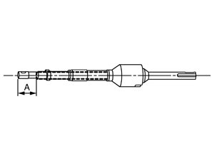
- 10.Separate the lower shaft from the steering gear assembly by sliding the slide shaft (A: sliding range).
■ CAUTION ■
Spiral cable may be cut if steering wheel turns while separating steering column assembly and steering gear assembly. Always fix the steering wheel using string to avoid turning.- 11.Remove the mounting bolts and nuts of steering gear assembly.
- 12.Support front suspension member with a suitable jack.
- 13.Remove front suspension member bolts and nuts. Refer to Exploded View.
- 14.Lower the suitable jack for the front suspension member.
- 15.Remove steering gear assembly.
INSTALLATIONNote the following, and install in the reverse order of removal.
■ CAUTION ■
Spiral cable may be cut if steering wheel turns while separating steering column assembly and steering gear assembly. Always fix the steering wheel using string to avoid turning.- When installing lower joint to steering gear assembly, follow the procedure listed below.
- Set rack of steering gear in the neutral position.NOTE:To get the neutral position of rack, turn gear-sub assembly and measure the distance of inner socket, and then measure the intermediate position of the distance.
- Align rear cover cap projection (A) with the marking position of gear housing assembly (B).
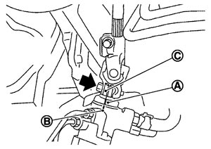

: Bolt - Install slit part of lower joint (C) aligning with the rear cover cap projection (A). Make sure that the slit part of lower joint (C) is aligned with rear cover cap projection (A) and the marking position of gear housing assembly (B).
- After installation, bleed air from the steering hydraulic system. Refer to Inspection.
- Perform final tightening of nuts and bolts on each part under unladen conditions with tires on level ground when removing steering gear assembly. Check wheel alignment. Refer to Inspection.
- Adjust neutral position of steering angle sensor after checking wheel alignment. Refer to Special Repair Requirement (GT-R certified NISSAN dealer).
Disassembly and Assembly
DISASSEMBLY- 1.Remove low pressure piping.
- Disassemble and assemble steering gear assembly by fixing the mounting area with a vise using copper plates.
- Clean steering gear assembly with kerosene before disassembling. Be careful to avoid splashing or applying any kerosene over connector of discharge port or return port.
■ CAUTION ■
- 2.Remove cylinder tubes from gear housing assembly.
- 3.Remove rear cover cap from gear-sub assembly.
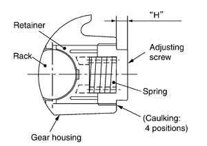
- 4.Measure adjusting screw height “H”, and loosen adjusting screw.
- Never loosen adjusting screw 2 turns or more.
- Replace steering gear assembly if adjusting screw is loosened 2 turns or more and it is removed.
■ CAUTION ■
- 5.Remove gear-sub assembly from gear housing assembly.
- 6.Remove O-ring from gear housing assembly.
- 7.Loosen outer socket lock nut, and remove outer socket.
- 8.Remove boot clamps, and then remove boot from inner socket.
■ CAUTION ■
Never damage inner socket and gear housing assembly when removing boot. Inner socket and gear housing assembly must be replaced if inner socket and gear housing assembly are damaged because it may cause foreign material interfusion.- 9.Remove inner socket from gear housing assembly.
- 10.Remove spacer from gear housing assembly.
ASSEMBLY- 1.Apply recommended fluid to O-ring, and then install O-ring to gear housing assembly.
■ CAUTION ■
Never reuse O-ring.- 2.Install gear-sub assembly to gear housing assembly.
■ CAUTION ■
In order to protect oil seal from any damage, insert gear-sub assembly straightly.- 3.Install inner socket to gear housing assembly with the following procedure.
-
(1)Install spacer to gear housing assembly.
-
(2)Apply thread sealant into the thread of inner socket.Use Genuine Medium Strength Thread Locking Sealant or equivalent. Refer to Recommended Chemical Products and Sealants.
- 4.Decide on the neutral position of the rack stroke (L).
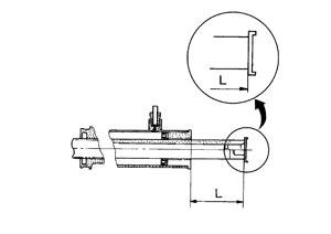
| Standard | |
| L | : Refer to Rack Stroke (GT-R certified NISSAN dealer) . |
- 5.Install rear cover cap to gear sub-assembly.
■ CAUTION ■
Check that the projection of rear cover cap is aligned with the marking position of gear housing assembly.- 6.Apply recommended thread sealant to the thread (2 turns thread), and then screw in the adjusting screw until it reaches height “H” from gear housing assembly measured before disassembling.
Use Genuine High Performance Thread Sealant or equivalent. Refer to Recommended Chemical Products and Sealants.
- 7.Move rack assembly 10 strokes throughout the full stroke so that the parts can fit with each other.
- 8.Adjust pinion rotating torque with the following procedure.
- If reading is outside of the specification, readjust screw angle with adjusting screw.■ CAUTION ■
- If reading is still outside of specification, or if the rotating torque of adjusting screw is less than 5 N·m (0.51 kg-m, 44 in-lb), replace steering gear assembly.
- Never turn adjusting screw more than twice.
- Replace steering gear assembly when adjusting screw is removed or turned more than twice.
- If reading is still outside of specification, or if the rotating torque of adjusting screw is less than 5 N·m (0.51 kg-m, 44 in-lb), replace steering gear assembly.
-
(1)Measure pinion rotating torque within ±180° of neutral position of the rack assembly using tools. Stop the gear at the point where highest torque is read.
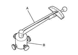
| A: Preload gauge [SST: ST3127S000 (J-25765-A)] | |
| B: Preload adapter [SST: KV48103400 ( — )] |
-
(2)Loosen adjusting screw and retighten to 5.4 N·m (0.55 kg‐m, 48 in‐lb), and then loosen by 20 to 40°.
-
(3)Measure pinion rotating torque using tools to check that the measured value is within the specified value. Readjust if the value is outside the standard. Replace steering gear assembly, if the value is out of the specified value after readjusting, or adjusting screw rotating torque is 5 N·m (0.51 kg-m, 44 in-lb) or less.
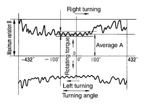
| Pinion rotating torque | ||
| Around neutral position (within±100°) average (A) | : 1.3 – 2.5 N·m (0.14 – 0.25 kg-m, 12 – 22 in-lb) | |
| Maximum variation (B) | : 3.0 N·m (0.31 kg‐m, 27 in‐lb) | |
-
(4)Apply thread sealant to inner socket and turn pinion fully to left with inner socket installed to gear housing assembly.
-
(5)Install dial gauge at 5 mm (0.20 in) (L) from the edge of gear housing assembly (1), and tooth point.
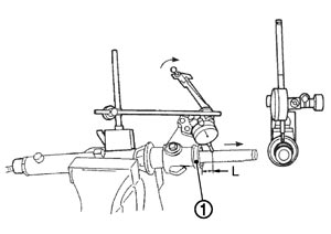
-
(6)Measure vertical movement of rack assembly when pinion is turned clockwise with torque of 19.6 N·m (2.0 kg‐m, 14 ft‐lb). Readjust adjusting screw angle if the measured value is out of the specified value.
| Vertical movement | : 0.265 mm (0.0104 in) |
- 9.Install large end of boot to gear housing assembly.
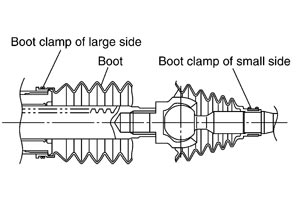
- 10.Install small end of boot to inner socket boot mounting groove.
- 11.Install boot clamp to boot small end.
- 12.Install boot clamp to the large side of boot with the following procedure.
■ CAUTION ■
Never reuse boot clamp.-
(1)Tighten large side of boot with boot clamp (stainless wire).
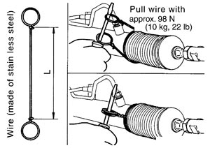
| Wire length (L) | : 370 mm (14.57 in) |
-
(2)Wrap clamp around boot groove for two turns. Insert a flat-bladed screwdriver in loops on both ends of wire. Twist 4 to 4.5 turns while pulling them with force of approximately 98 N (10 kg, 22 lb).
-
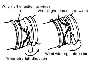
(3)Twist boot clamp as shown. Pay attention to relationship between winding and twisting directions.
-
(4)Twisted area of clamp (A) is on the opposite side of adjusting screw (1) as shown in the figure. (To prevent contact with other parts)
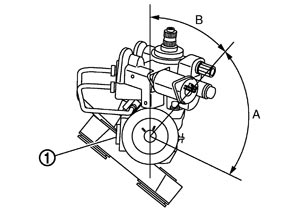
| A | : 90° |
| B | : 45° |
-
(5)Bend cut end of the wire within the area (A) shown in the figure after twisting the wire 4 to 4.5 turns so that the cut end does not contact with boot.
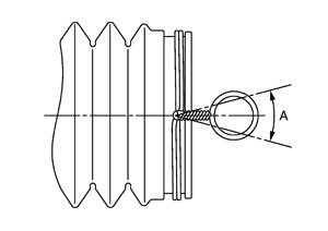
■ CAUTION ■
Keep the clearance from cylinder tube 5.0 mm or more. | A | : 30° |
- 13.Install cylinder tubes to gear housing assembly.
■ CAUTION ■
Never reuse copper washers.- 14.Install low pressure piping.
- 15.Adjust inner socket to standard length (L), and then tighten lock nut to the specified torque. Check length again after tightening lock nut.
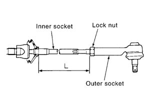
| Standard | |
| L | : Refer to Inner Socket Length (GT-R certified NISSAN dealer). |
■ CAUTION ■
Adjust toe-in after this procedure. The length achieved after toe-in adjustment is not necessary the above value.Inspection
INSPECTION AFTER INSTALLATION- Check if steering wheel turns smoothly when it is turned several times fully to the end of the left and right.
- Check the steering wheel play, neutral position steering wheel, steering wheel turning force, and front wheel turning angle. Refer to Inspection.
- Check the fluid level, fluid leakage, and air bleeding hydraulic system. Refer to Inspection.
INSPECTION AFTER DISASSEMBLY Boot
BootCheck boot for cracks, and replace it if a malfunction is detected.
Rack AssemblyCheck rack for damage or wear, and replace it if a malfunction is detected.
Gear-Sub Assembly- Check gear-sub assembly for damage or wear, and replace it if a malfunction is detected.
- Rotate gear-sub assembly and check for torque variation or rattle, and replace it if a malfunction is detected.
Gear Housing AssemblyCheck gear housing assembly for damage and scratches (inner wall). Replace if there are.
Outer Socket and Inner SocketCheck the following items and replace the component if it does not meet the standard.
BALL JOINT SWINGING TORQUEHook a spring balance at the point shown in the figure and pull the spring balance. Make sure that the spring balance reads the specified value when ball stud and inner socket start to move. Replace outer socket and inner socket if they are outside the standard.
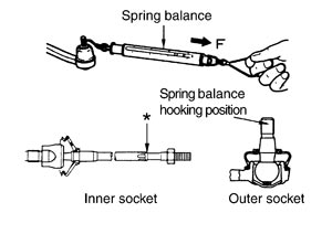
| Standard | ||
| (Measuring point of outer socket: Stud cotter pin mounting hole) | ||
| Outer socket | : Refer to Socket Swing Force and Rotating Torque (GT-R certified NISSAN dealer). | |
| Standard | ||
| (Measuring point of inner socket: “*” mark shown in the figure) | ||
| Inner socket | : Refer to Socket Swing Force and Rotating Torque (GT-R certified NISSAN dealer). | |
BALL JOINT ROTATING TORQUEMake sure that the reading is within the following specified range using preload gauge (A) [SST: ST3127S000 (J-25765-A)]. Replace outer socket if the reading is outside the specified value.
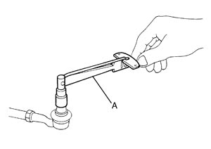
| Standard | |
| Rotating torque | : Refer to Socket Swing Force and Rotating Torque (GT-R certified NISSAN dealer). |
BALL JOINT AXIAL END PLAYApply an axial load of 490 N (50 kg, 110 lb) to ball stud. Using a dial gauge, measure amount of stud movement, and then make sure that the value is within the following specified range. Replace outer socket (1) and inner socket (2) if the measured value is outside the standard.
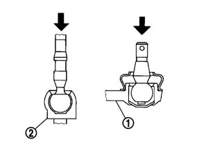
| Standard | |
| Outer socket | : Refer to Socket Axial End Play (GT-R certified NISSAN dealer). |
| Inner socket | : Refer to Socket Axial End Play (GT-R certified NISSAN dealer). |