POWER STEERING OIL PUMP
Exploded View
 REMOVAL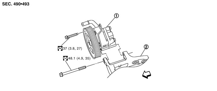
|
1. |
Power steering oil pump |
2. |
Bracket |
|
|
 : Vehicle front : Vehicle front |
|||||
|
Refer to Components for symbols in the figure. |
|||||
DISASSEMBLY 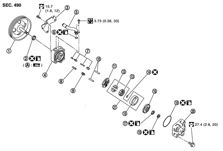
|
1. |
Pulley |
2. |
Oil seal |
3. |
Bracket |
|
4. |
Body assembly |
5. |
Suction pipe |
6. |
O-ring |
|
7. |
Flow control valve B assembly |
8. |
Flow control valve spring |
9. |
Flow control valve A |
|
10. |
Dowel pin |
11. |
Front side plate |
12. |
Vane |
|
13. |
Rotor |
14. |
Rotor snap ring |
15. |
Cam ring |
|
16. |
Rear side plate |
17. |
O-ring |
18. |
Teflon ring |
|
19. |
O-ring |
20. |
Rear cover |
21. |
Cartridge |
|
A. |
Oil seal lip |
|
|
|
|
 : Apply power steering fluid. : Apply power steering fluid. |
|||||
 : Apply multi-purpose grease. : Apply multi-purpose grease. |
|||||
|
Refer to Components for symbols not described on the above. |
|||||
Removal and Installation
REMOVAL- 1.Drain power steering fluid from reservoir tank.
- 2.Remove the right of the air cleaner and the right of the air duct. Refer to Exploded View.
- 3.Loosen drive belt. Refer to Exploded View.
- 4.Remove drive belt from oil pump pulley.
- 5.Remove pressure sensor connector.
- 6.Remove copper washers and eye bolt (drain fluid from their pipings).
- 7.Remove suction hose (drain fluid from their pipings).
- 8.Remove oil pump mounting bolts, and then remove oil pump.
INSTALLATIONNote the following, and install in the reverse order of removal.
- When installing suction hoses (1), refer to the figure.
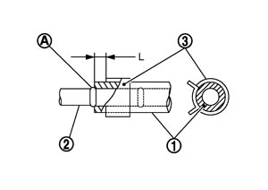 ■ CAUTION ■
- Never apply fluid to the hose (1) and tube (2).
- Insert hose securely until it contacts spool (A) of tube.
- Leave clearance (L) when installing clamp (3).
Standard L : 3 – 8 mm (0.12 – 0.31 in)
- Never apply fluid to the hose (1) and tube (2).
- When installing eye bolt (1) and copper washer (2) to oil pump (3), refer to the figure.
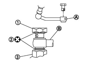 ■ CAUTION ■
- Never reuse copper washer.
- Apply power steering fluid to around copper washers, then install eye bolt.
- Install eye bolt with eye joint (assembled to high pressure hose) (B) protrusion (A) facing with pump side cutout, and then tighten it to the specified torque after tightening by hand. Refer to Exploded View.
- Securely insert harness connector to pressure sensor.
- Never reuse copper washer.
- Adjust belt tension. Refer to Tension Adjustment (GT-R certified NISSAN dealer).
- Check fluid level, fluid leakage and air bleeding hydraulic system after the installation. Refer to Inspection.
Disassembly and Assembly
DISASSEMBLY- 1.Remove rear cover mounting bolts, and then remove rear cover from body assembly.
- Fix oil pump with a vise if necessary.
- Use copper plates when fixing with a vise.
■ CAUTION ■
- 2.Remove O-ring from body assembly.
- 3.Remove rear side plate from cartridge, and then remove Teflon ring and O-ring from rear side plate.
- 4.Remove rotor snap ring using a snap ring pliers, and remove pulley from body assembly.
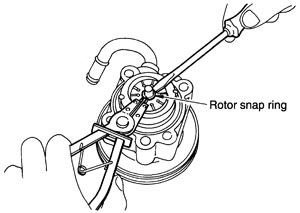
■ CAUTION ■
Be careful not to damage pulley, when removing rotor snap ring.- 5.Remove cartridge and front side plate.
- 6.Remove flow control valve A, flow control valve spring and flow control valve B assembly from body assembly.
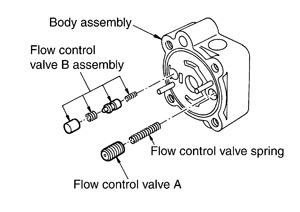
■ CAUTION ■
Never drop and damage flow control valve A and flow control valve B assembly when removing.- 7.Remove oil seal from body assembly.
- 8.Remove mounting bolt of suction pipe, and then remove suction pipe from body assembly.
- 9.Remove O-ring from body assembly.
- 10.Remove bracket mounting bolts, and then remove bracket from body assembly.
ASSEMBLY- 1.Apply recommended grease to oil seal lips. Apply recommended fluid to around oil seal, and then install oil seal to body assembly using a drift [SST: ST35300000 ( — )]
- Fix oil pump with a vise if necessary.
- Use copper plates when fixing with a vise.
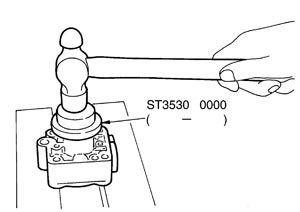
■ CAUTION ■
- 2.Install bracket to body assembly.
- 3.If dowel pin has been removed, insert it into body assembly by hand. If it cannot be inserted by hand, lightly tap with a hammer.
- 4.Install flow control valve A, flow control valve spring and flow control valve B assembly to body assembly.
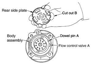
- 5.Install front side plate (3) with dowel pin (2) on flow control valve A (1) side as shown in the figure aligning with front side plate cutout (A) to body assembly (4).
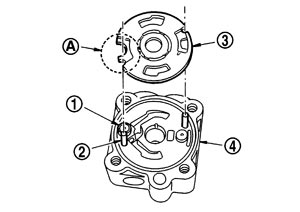
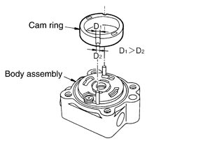
- 6.Install cam ring as shown in the figure.
- 7.Install pulley to body assembly.
■ CAUTION ■
Never damage oil seal when installing pulley.- 8.Be careful with the orientation of rotor, and then install it to pulley shaft.
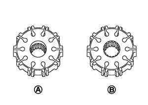
| A | :Rear cover side |
| B | :Body assembly side |
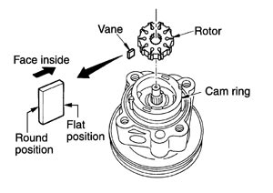
- 9.Install vane to rotor so that arc of vane faces cam ring side.
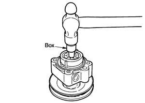
- 10.Install rotor snap ring to slit of pulley shaft using a hammer and a 10 mm (0.39 in) box.
- Never damage rotor and pulley shaft.
- Oil pump assembly must be replaced if rotor is damaged.
■ CAUTION ■
- 11.Install rear side plate with dowel pin A on flow control valve A side as shown in the figure aligning with rear side plate cutout B to cartridge.
- 12.Apply recommended fluid to O-ring, and then install O-ring to body assembly.
- 13.Apply recommended fluid to O-ring, and then install O-ring to rear side plate.
- 14.Apply recommended fluid to Teflon ring, and then install Teflon ring to rear side plate.
- 15.Install rear cover to body assembly.
- 16.Apply recommended fluid to O-ring, and then install O-ring to body assembly.
- 17.Install suction pipe to body assembly.
Inspection
RELIEF OIL PRESSURE■ CAUTION ■
Check that belt tension is normal before starting the following procedure.
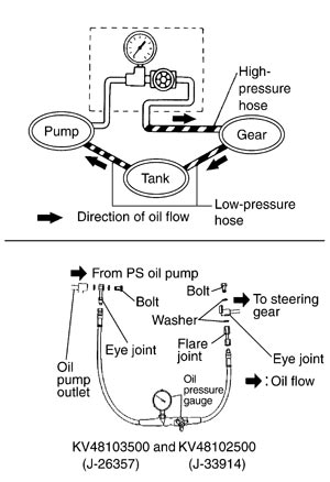
- 1.Connect the oil pressure gauge [SST: KV48103500 (J-26357)] and the oil pressure gauge adapter [SST: KV48102500 (J-33914)] between oil pump discharge connector and high-pressure hose. Bleed air from the hydraulic circuit while opening valve fully. Refer to Inspection.
- 2.Start engine. Run engine until oil temperature reaches 50 to 80°C (122 to 176°F).
- Leave the valve of the oil pressure gauge fully open while starting and running engine. If engine is started with the valve closed, the hydraulic pressure in oil pump goes up to the relief pressure along with unusual increase of oil temperature.
- Always keep hose clear of belts and other parts when engine is started.
■ CAUTION ■
- 3.Fully close the oil pressure gauge valve with engine at idle and measure the relief oil pressure.
| Standard | |
| Relief oil pressure | : Refer to Relief Oil Pressure (GT-R certified NISSAN dealer). |
■ CAUTION ■
Never keep valve fully closed for 10 seconds or longer.- 4.Open the valve slowly after measuring. Repair oil pump if the relief oil pressure is outside the standard. Refer to Disassembly and Assembly (GT-R certified NISSAN dealer).
- 5.Disconnect the oil pressure gauge from hydraulic circuit.
- 6.When installing eye bolt (1) and copper washer (2) to oil pump (3), refer to the figure.
- Never reuse copper washers.
- Apply power steering fluid or equivalent to around copper washer, then install eye bolt.
- Install eye bolt with eye joint (assembled to high pressure hose) (B) protrusion (A) facing with pump side cutout, and then tighten it to the specified torque after tightening by hand. Refer to Exploded View.
- Securely insert harness connector to pressure sensor.
■ CAUTION ■
- 7.Check fluid level, fluid leakage and air bleeding hydraulic system after the installation. Refer to Inspection.
BEFORE DISASSEMBLYDisassemble oil pump only when the following malfunctions occur.
- If oil leakage is found on oil pump.
- Oil pump pulley is damaged or deformed.
- Performance of oil pump is low.
AFTER DISASSEMBLY Body Assembly and Rear Cover Inspection
Check body assembly and rear cover for internal damage. Replace rear cover if it is damaged. Replace oil pump assembly if body assembly is damaged.
Cartridge Assembly InspectionCheck cam ring, rotor and vane for damage. Replace cartridge assembly if necessary.
Side Plate InspectionCheck side plate for damage. Replace side plate if there are.
Flow Control Valve InspectionCheck flow control valve and spring for damage. Replace if necessary.