ELECTRIC IGNITION SYSTEM
VR38
System Diagram
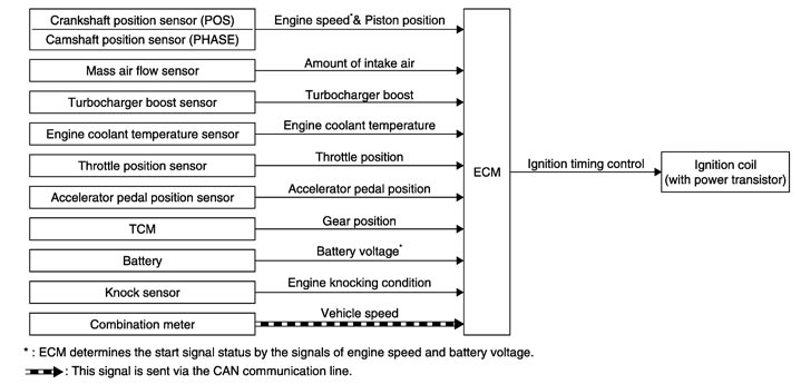
System Description
 INPUT/OUTPUT SIGNAL CHART
|
Sensor |
Input Signal to ECM |
ECM function |
Actuator |
|
Crankshaft position sensor (POS) |
Engine speed*2 Piston position |
Ignition timing control |
Ignition coil (with power transistor) |
|
Camshaft position sensor (PHASE) |
|||
|
Mass air flow sensor |
Amount of intake air |
||
|
Turbochager boost sensor |
Turbochager boost |
||
|
Engine coolant temperature sensor |
Engine coolant temperature |
||
|
Throttle position sensor |
Throttle position |
||
|
Accelerator pedal position sensor |
Accelerator pedal position |
||
|
TCM |
Gear position |
||
|
Battery |
Battery voltage*2 |
||
|
Knock sensor |
Engine knocking |
||
|
Combination meter. |
Vehicle speed*1 |
SYSTEM DESCRIPTIONIgnition order: 1 - 2 - 3 - 4 - 5 - 6
The ignition timing is controlled by the ECM to maintain the best air-fuel ratio for every running condition of the engine. The ignition timing data is stored in the ECM.
The ECM receives information such as the injection pulse width and camshaft position sensor (PHASE) signal. Computing this information, ignition signals are transmitted to the power transistor.
During the following conditions, the ignition timing is revised by the ECM according to the other data stored in the ECM.
- At starting
- During warm-up
- At idle
- At low battery voltage
- During acceleration
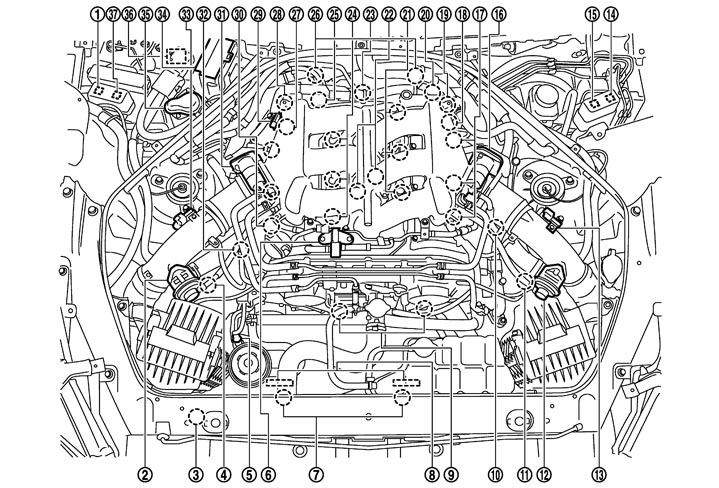
Component Parts Location
|
1. |
Air cut solenoid valve relay |
2. |
Recirculation valve (bank 1) |
3. |
Refrigerant pressure sensor |
|
4. |
Mass air flow sensor (with intake air temperature sensor) (bank 1) |
5. |
Power steering pressure sensor |
6. |
EVAP canister purge volume control solenoid valve |
|
7. |
Cooling fan motor |
8. |
Cooling fan control module |
9. |
Intake valve timing control solenoid valve |
|
10. |
Turbocharger boost control solenoid valve |
11. |
Mass air flow sensor (with intake air temperature sensor) (bank 2) |
12. |
Recirculation valve (bank 2) |
|
13. |
Turbocharger boost sensor (bank 2) |
14. |
Cooling fan relay-1 |
15. |
Cooling fan relay-2 |
|
16. |
Electric throttle control actuator (bank 2) |
17. |
Ignition coil (with power transistor) and spark plug (bank 2) |
18. |
Camshaft position sensor (PHASE) (bank 2) |
|
19. |
Air cut solenoid valve (bank 2) |
20. |
Crankshaft position sensor (POS) |
21. |
Fuel injector (bank 2) |
|
22. |
Knock sensor |
23. |
Engine oil temperature sensor |
24. |
Fuel injector (bank 1) |
|
25. |
Engine coolant temperature sensor |
26. |
A/F sensor 1 (bank 1) |
27. |
Camshaft position sensor (PHASE) (bank 1) |
|
28. |
Air cut solenoid valve (bank 1) |
29. |
Manifold absolute pressure sensor |
30. |
Ignition coil (with power transistor) and spark plug (bank 1) |
|
31. |
Electric throttle control actuator (bank 1) |
32. |
EVAP service port |
33. |
Turbocharger boost sensor (bank 1) |
|
34. |
IPDM E/R |
35. |
Air pump cleaner |
36. |
Air pump |
|
37. |
Air pump relay |
|
|
|
|
|
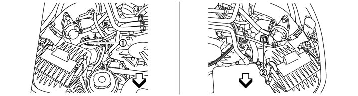
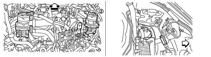
1. |
Mass air flow sensor (with intake air temperature sensor) (bank 1) |
2. |
Mass air flow sensor (with intake air temperature sensor) (bank 2) |
|
|

|
:Vehicle front |
|
|
|
|
|
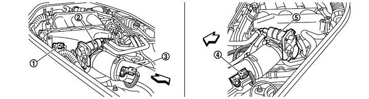
1. |
Manifold absolute pressure sensor |
2. |
Electric throttle control actuator (bank 1) |
3. |
Turbocharger boost sensor (bank 1) |
|
4. |
Turbocharger boost sensor (bank 2) |
5. |
Electric throttle control actuator (bank 2) |
|
|
|
|
:Vehicle front |
|
|
|
|
|
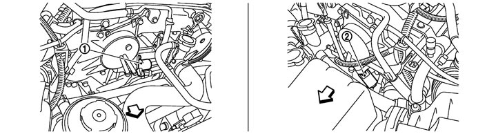
1. |
Intake valve timing control solenoid valve (bank1) |
2. |
Intake valve timing control solenoid valve (bank2) |
|
|
|
|
:Vehicle front |
|
|
|
|
|
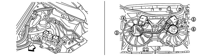
1. |
Cooling fan relay-2 |
2. |
Cooling fan relay-1 |
3. |
Cooling fan motor-1 |
|
4. |
Cooling fan control module-1 |
5. |
Cooling fan control module-2 |
6. |
Cooling fan motor-2 |
|
|
:Vehicle front |
|
|
|
|
|
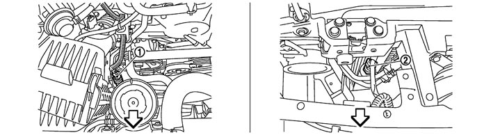
1. |
Power steering pressure sensor |
2. |
Refrigerant pressure sensor |
|
|
|
|
:Vehicle front |
|
|
|
|
|
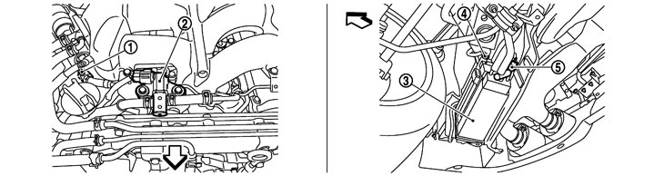
1. |
EVAP service port |
2. |
EVAP canister purge volume control solenoid valve |
3. |
EVAP canister |
|
4. |
EVAP control system pressure sensor |
5. |
EVAP canister vent control valve |
|
|
|
|
:Vehicle front |
|
|
|
|
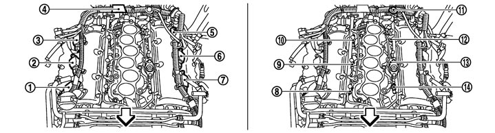
|
1. |
Ignition coil No.1 (with power transistor) |
2. |
Ignition coil No.3 (with power transistor) |
3. |
Ignition coil No.5 (with power transistor) |
|
4. |
Condenser |
5. |
Ignition coil No.6 (with power transistor) |
6. |
Ignition coil No.4 (with power transistor) |
|
7. |
Ignition coil No.2 (with power transistor) |
8. |
Fuel injector No.1 |
9. |
Fuel injector No.3 |
|
10. |
Fuel injector No.5 |
11. |
Fuel pressure regulator |
12. |
Fuel injector No.6 |
|
13. |
Fuel injector No.4 |
14. |
Fuel injector No.2 |
|
|
|
|
:Vehicle front |
|
|
|
|
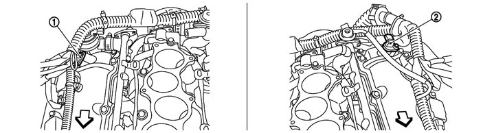
|
1. |
Camshaft position sensor (PHASE) (bank 1) |
2. |
Camshaft position sensor (PHASE) (bank 2) |
|
|
|
|
:Vehicle front |
|
|
|
|
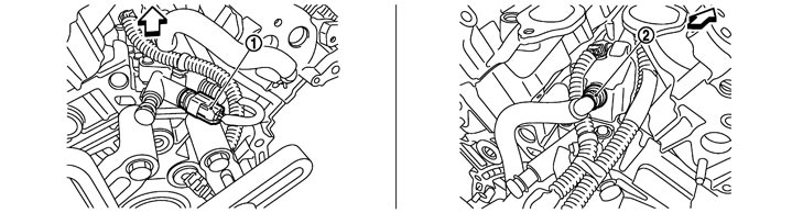
|
1. |
Engine oil temperature sensor |
2. |
PCV valve |
|
|
|
|
:Vehicle front |
|
|
|
|
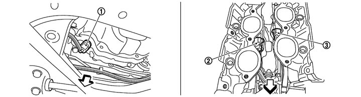
|
1. |
Crankshaft position sensor (POS) |
2. |
Knock sensor (bank1) |
3. |
Knock sensor (bank2) |
|
|
:Vehicle front |
|
|
|
|
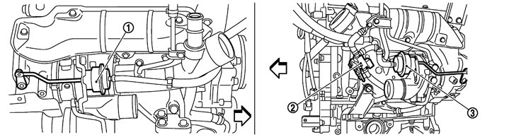
|
1. |
Boost control actuator (bank1) |
2. |
Turbocharger boost control solenoid valve |
3. |
Boost control actuator (bank2) |
|
|
:Vehicle front |
|
|
|
|
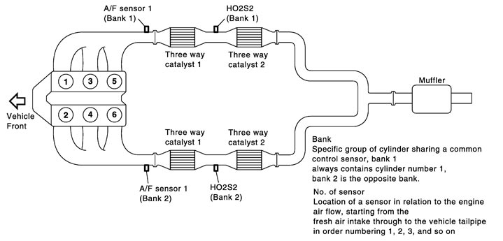
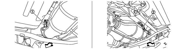
|
1. |
Heated oxygen sensor 2 (bank 2) |
2. |
Heated oxygen sensor 2 (bank 1) |
|
|
|
|
:Vehicle front |
|
|
|
|
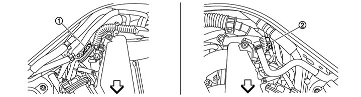
|
1. |
A/F sensor 1 (bank 1) harness connector |
2. |
A/F sensor 1 (bank 2) harness connector |
|
|
|
|
:Vehicle front |
|
|
|
|
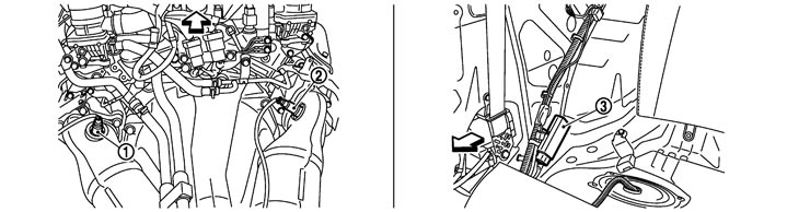
|
1. |
A/F sensor 1 (bank 2) |
2. |
A/F sensor 1 (bank 1) |
3. |
Fuel pump control module (FPCM) |
|
|
:Vehicle front |
|
|
|
|
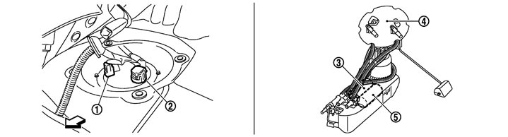
|
1. |
Sub fuel pump harness connector |
2. |
Main fuel gauge fuel filter fuel pump assembly harness connector |
3. |
Sub fuel pump |
|
4. |
Main fuel gauge fuel filter fuel pump assembly |
5. |
Fuel pump |
|
|
|
|
:Vehicle front |
|
|
|
|
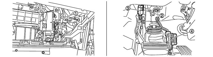
|
1. |
ECM |
2. |
Brake switch |
3. |
Stop lamp switch |
|
4. |
Accelerator pedal position sensor |
|
|
|
|
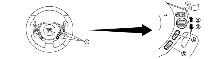
|
1. |
ASCD steering switch |
2. |
RESUME/ACCELERATE switch |
3. |
SET/COAST switch |
|
4. |
CANCEL switch |
5. |
MAIN switch |
|
|
|
1. |
Air cut solenoid valve (bank 2) |
2. |
Air cut solenoid valve (bank 1) |
3. |
Engine coolant temperature sensor |
|
4. |
Air pump |
5. |
Secondary air injection system mass air flow sensor |
|
|
|
|
:Vehicle front |
|
|
|
|

|
1. |
Air cut solenoid valve relay |
2. |
Air pump relay |
3. |
Air pump cleaner |
|
4. |
IPDM E/R |
|
|
|
|
Component Description
|
Component |
Reference |
|
Accelerator pedal position sensor |
Description (GT-R certified NISSAN dealer)
|
|
Camshaft position sensor (PHASE) |
Description (GT-R certified NISSAN dealer)
|
|
Crankshaft position sensor (POS) |
Description (GT-R certified NISSAN dealer)
|
|
Engine coolant temperature sensor |
Description (GT-R certified NISSAN dealer)
|
|
Knock sensor |
Description (GT-R certified NISSAN dealer)
|
|
Mass air flow sensor |
Description (GT-R certified NISSAN dealer)
|
|
Throttle position sensor |
Description (GT-R certified NISSAN dealer)
|
|
Turbocharger boost sensor |
Description (GT-R certified NISSAN dealer)
|