AUTOMATIC SPEED CONTROL DEVICE (ASCD)
VR38
System Diagram
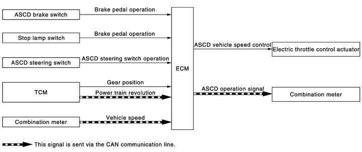
System Description
 INPUT/OUTPUT SIGNAL CHART
|
Sensor |
Input signal to ECM |
ECM function |
Actuator |
|
ASCD brake switch |
Brake pedal operation |
|
|
|
Stop lamp switch |
Brake pedal operation |
||
|
ASCD steering switch |
ASCD steering switch operation |
||
|
TCM |
Gear position Powertrain revolution* |
||
|
Combination meter |
Vehicle speed* |
BASIC ASCD SYSTEMRefer to Owner's Manual for ASCD operating instructions.
Automatic Speed Control Device (ASCD) allows a driver to keep vehicle at predetermined constant speed without depressing accelerator pedal. Driver can set vehicle speed in advance between approximately 40 km/h (25 MPH) and 250 km/h (156 MPH).
ECM controls throttle angle of electric throttle control actuator to regulate vehicle speed.
Operation status of ASCD is indicated by CRUISE lamp and SET lamp in combination meter. Refer to Description (GT-R certified NISSAN dealer). The operation status is also indicated on the information display in the combination meter. Refer to Description (GT-R certified NISSAN dealer). If any malfunction occurs in the ASCD system, it automatically deactivates control.
NOTE:
Always drive vehicle in a safe manner according to traffic conditions and obey all traffic laws. SET OPERATIONPress MAIN switch. (The CRUISE lamp in combination meter illuminates.)
When vehicle speed reaches a desired speed between approximately 40 km/h (25 MPH) and 250 km/h (156 MPH), press SET/COAST switch. (Then SET lamp in combination meter illuminates.)
ACCELERATE OPERATIONIf the RESUME/ACCELERATE switch is pressed during cruise control driving, increase the vehicle speed until the switch is released or vehicle speed reaches maximum speed controlled by the system.
And then ASCD will maintain the new set speed.
CANCEL OPERATIONWhen any of following conditions exist, cruise operation will be canceled.
- MAIN switch is pressed (Set speed will be cleared)
- CANCEL switch is pressed
- More than 2 switches at ASCD steering switch are pressed at the same time (Set speed will be cleared)
- Brake pedal is depressed
- Selector lever position is P, N or R
- Vehicle speed decreased to 13 km/h (8 MPH) lower than the set speed
- VDC system is operated
- When the vehicle speed is approximately 30 km/h (19 MPH) or less
- Engine coolant temperature is slightly higher than the normal operating temperature, CRUISE lamp may blink slowly.When the engine coolant temperature decreases to the normal operating temperature, CRUISE lamp will stop blinking and the cruise operation will be able to work by pressing SET/COAST switch or RESUME/ACCELERATE switch.
- Malfunction for some self-diagnoses regarding ASCD control: SET lamp will blink quickly.
COAST OPERATIONWhen the SET/COAST switch is pressed during cruise control driving, decrease vehicle set speed until the switch is released. And then ASCD will keep the new set speed.
RESUME OPERATIONWhen the RESUME/ACCELERATE switch is pressed after canceling operation other than pressing the MAIN switch, vehicle speed will return to last set speed. To resume vehicle set speed, vehicle condition must meet following conditions.
- Brake pedal is released
- Selector lever position is other than P, N and R
- Vehicle speed is greater than 40 km/h (25 MPH) and less than 250 km/h (156 MPH)
Component Parts Location
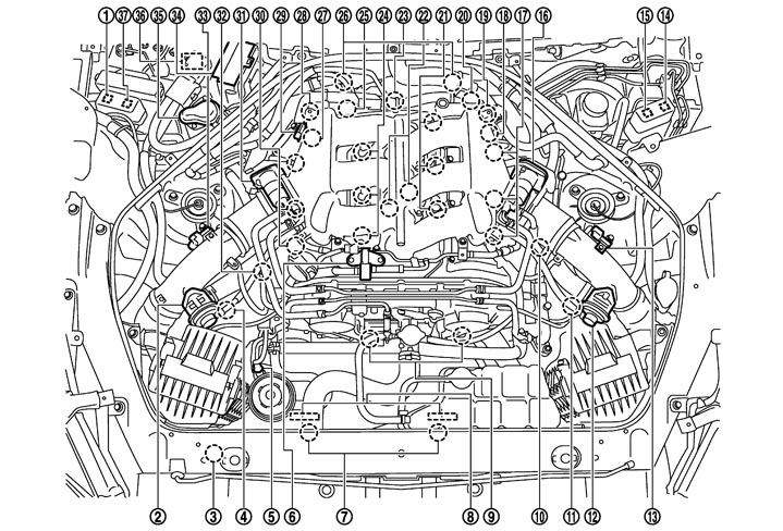
|
1. |
Air cut solenoid valve relay |
2. |
Recirculation valve (bank 1) |
3. |
Refrigerant pressure sensor |
|
4. |
Mass air flow sensor (with intake air temperature sensor) (bank 1) |
5. |
Power steering pressure sensor |
6. |
EVAP canister purge volume control solenoid valve |
|
7. |
Cooling fan motor |
8. |
Cooling fan control module |
9. |
Intake valve timing control solenoid valve |
|
10. |
Turbocharger boost control solenoid valve |
11. |
Mass air flow sensor (with intake air temperature sensor) (bank 2) |
12. |
Recirculation valve (bank 2) |
|
13. |
Turbocharger boost sensor (bank 2) |
14. |
Cooling fan relay-1 |
15. |
Cooling fan relay-2 |
|
16. |
Electric throttle control actuator (bank 2) |
17. |
Ignition coil (with power transistor) and spark plug (bank 2) |
18. |
Camshaft position sensor (PHASE) (bank 2) |
|
19. |
Air cut solenoid valve (bank 2) |
20. |
Crankshaft position sensor (POS) |
21. |
Fuel injector (bank 2) |
|
22. |
Knock sensor |
23. |
Engine oil temperature sensor |
24. |
Fuel injector (bank 1) |
|
25. |
Engine coolant temperature sensor |
26. |
A/F sensor 1 (bank 1) |
27. |
Camshaft position sensor (PHASE) (bank 1) |
|
28. |
Air cut solenoid valve (bank 1) |
29. |
Manifold absolute pressure sensor |
30. |
Ignition coil (with power transistor) and spark plug (bank 1) |
|
31. |
Electric throttle control actuator (bank 1) |
32. |
EVAP service port |
33. |
Turbocharger boost sensor (bank 1) |
|
34. |
IPDM E/R |
35. |
Air pump cleaner |
36. |
Air pump |
|
37. |
Air pump relay |
|
|
|
|
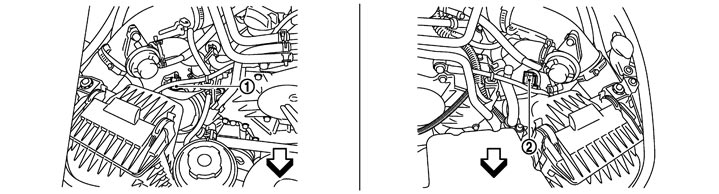
|
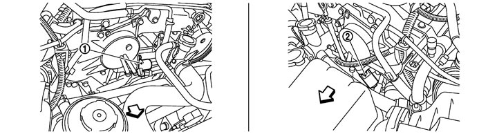
1. |
Mass air flow sensor (with intake air temperature sensor) (bank 1) |
2. |
Mass air flow sensor (with intake air temperature sensor) (bank 2) |
|
|

|
:Vehicle front |
|
|
|
|
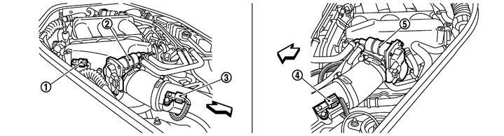
|
1. |
Manifold absolute pressure sensor |
2. |
Electric throttle control actuator (bank 1) |
3. |
Turbocharger boost sensor (bank 1) |
|
4. |
Turbocharger boost sensor (bank 2) |
5. |
Electric throttle control actuator (bank 2) |
|
|
|
|
:Vehicle front |
|
|
|
|
|
1. |
Intake valve timing control solenoid valve (bank1) |
2. |
Intake valve timing control solenoid valve (bank2) |
|
|
|
|
:Vehicle front |
|
|
|
|
|
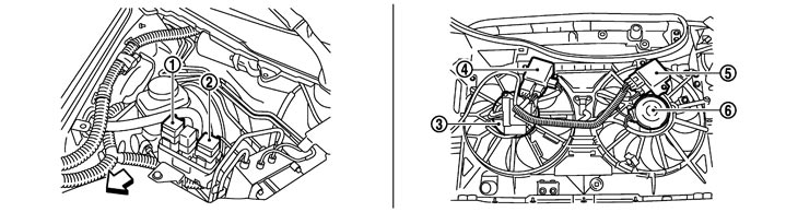
1. |
Cooling fan relay-2 |
2. |
Cooling fan relay-1 |
3. |
Cooling fan motor-1 |
|
4. |
Cooling fan control module-1 |
5. |
Cooling fan control module-2 |
6. |
Cooling fan motor-2 |
|
|
:Vehicle front |
|
|
|
|
|
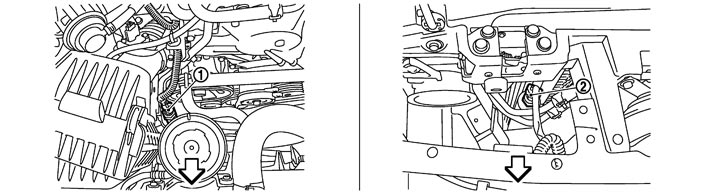
1. |
Power steering pressure sensor |
2. |
Refrigerant pressure sensor |
|
|
|
|
:Vehicle front |
|
|
|
|
|
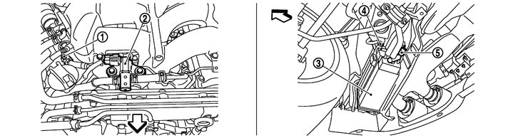
1. |
EVAP service port |
2. |
EVAP canister purge volume control solenoid valve |
3. |
EVAP canister |
|
4. |
EVAP control system pressure sensor |
5. |
EVAP canister vent control valve |
|
|
|
|
:Vehicle front |
|
|
|
|
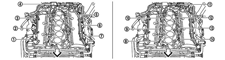
|
1. |
Ignition coil No.1 (with power transistor) |
2. |
Ignition coil No.3 (with power transistor) |
3. |
Ignition coil No.5 (with power transistor) |
|
4. |
Condenser |
5. |
Ignition coil No.6 (with power transistor) |
6. |
Ignition coil No.4 (with power transistor) |
|
7. |
Ignition coil No.2 (with power transistor) |
8. |
Fuel injector No.1 |
9. |
Fuel injector No.3 |
|
10. |
Fuel injector No.5 |
11. |
Fuel pressure regulator |
12. |
Fuel injector No.6 |
|
13. |
Fuel injector No.4 |
14. |
Fuel injector No.2 |
|
|
|
|
:Vehicle front |
|
|
|
|
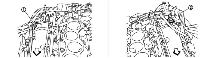
|
1. |
Camshaft position sensor (PHASE) (bank 1) |
2. |
Camshaft position sensor (PHASE) (bank 2) |
|
|
|
|
:Vehicle front |
|
|
|
|
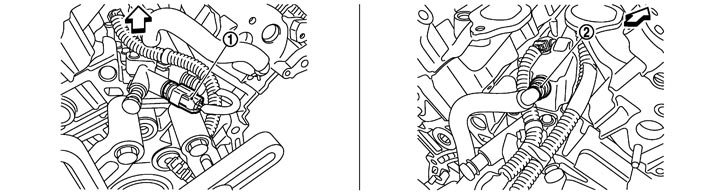
|
1. |
Engine oil temperature sensor |
2. |
PCV valve |
|
|
|
|
:Vehicle front |
|
|
|
|
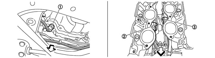
|
1. |
Crankshaft position sensor (POS) |
2. |
Knock sensor (bank1) |
3. |
Knock sensor (bank2) |
|
|
:Vehicle front |
|
|
|
|
|
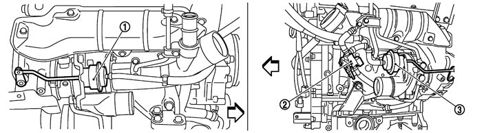
1. |
Boost control actuator (bank1) |
2. |
Turbocharger boost control solenoid valve |
3. |
Boost control actuator (bank2) |
|
|
:Vehicle front |
|
|
|
|
|
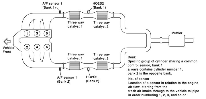
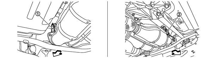
1. |
Heated oxygen sensor 2 (bank 2) |
2. |
Heated oxygen sensor 2 (bank 1) |
|
|
|
|
:Vehicle front |
|
|
|
|
|
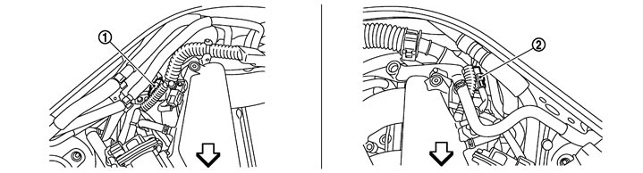
1. |
A/F sensor 1 (bank 1) harness connector |
2. |
A/F sensor 1 (bank 2) harness connector |
|
|
|
|
:Vehicle front |
|
|
|
|
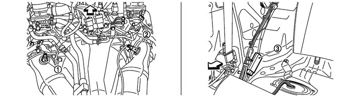
|
1. |
A/F sensor 1 (bank 2) |
2. |
A/F sensor 1 (bank 1) |
3. |
Fuel pump control module (FPCM) |
|
|
:Vehicle front |
|
|
|
|
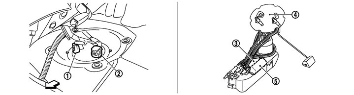
|
1. |
Sub fuel pump harness connector |
2. |
Main fuel gauge fuel filter fuel pump assembly harness connector |
3. |
Sub fuel pump |
|
4. |
Main fuel gauge fuel filter fuel pump assembly |
5. |
Fuel pump |
|
|
|
|
:Vehicle front |
|
|
|
|
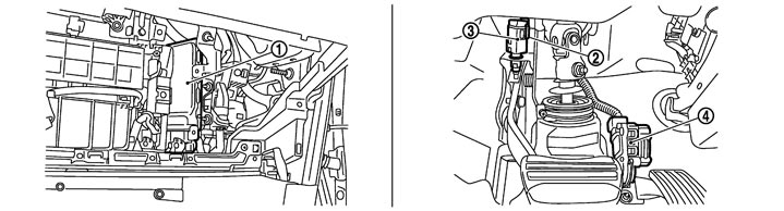
|
1. |
ECM |
2. |
Brake switch |
3. |
Stop lamp switch |
|
4. |
Accelerator pedal position sensor |
|
|
|
|
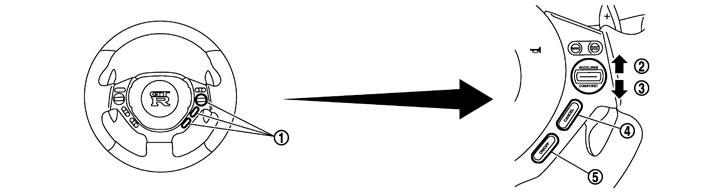
|
1. |
ASCD steering switch |
2. |
RESUME/ACCELERATE switch |
3. |
SET/COAST switch |
|
4. |
CANCEL switch |
5. |
MAIN switch |
|
|
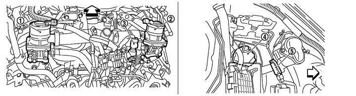
|
1. |
Air cut solenoid valve (bank 2) |
2. |
Air cut solenoid valve (bank 1) |
3. |
Engine coolant temperature sensor |
|
4. |
Air pump |
5. |
Secondary air injection system mass air flow sensor |
|
|
|
|
:Vehicle front |
|
|
|
|

|
1. |
Air cut solenoid valve relay |
2. |
Air pump relay |
3. |
Air pump cleaner |
|
4. |
IPDM E/R |
|
|
|
|
Component Description
|
Component |
Reference |
|
ASCD steering switch |
Description (GT-R certified NISSAN dealer)
|
|
ASCD brake switch |
Description (GT-R certified NISSAN dealer)
|
|
Stop lamp switch |
Description (GT-R certified NISSAN dealer)
|
|
Electric throttle control actuator |
Description (GT-R certified NISSAN dealer)
|
|
ASCD indicator |
Description (GT-R certified NISSAN dealer)
|