ON BOARD DIAGNOSTIC (OBD) SYSTEM
VR38
Diagnosis Description
 INTRODUCTION
The ECM has an on board diagnostic system, which detects malfunctions related to engine sensors or actuators. The ECM also records various emission-related diagnostic information including:
| Emission-related diagnostic information | Diagnostic service |
| Diagnostic Trouble Code (DTC) | Service $03 of SAE J1979 |
| Freeze Frame data | Service $02 of SAE J1979 |
| System Readiness Test (SRT) code | Service $01 of SAE J1979 |
| 1st Trip Diagnostic Trouble Code (1st Trip DTC) | Service $07 of SAE J1979 |
| 1st Trip Freeze Frame data | — |
| Test values and Test limits | Service $06 of SAE J1979 |
| Calibration ID | Service $09 of SAE J1979 |
The above information can be checked using procedures listed in the table below.
| DTC | 1st trip DTC | Freeze Frame data | 1st trip Freeze Frame data | SRT code | SRT status | Test value | |
| CONSULT-III | × | × | × | × | × | × | — |
| GST | × | × | × | — | × | × | × |
| ECM | × | ×* | — | — | — | × | — |
The malfunction indicator lamp (MIL) on the instrument panel lights up when the same malfunction is detected in two consecutive trips (Two trip detection logic), or when the ECM enters fail-safe mode. (Refer to Fail Safe (GT-R certified NISSAN dealer).)
TWO TRIP DETECTION LOGICWhen a malfunction is detected for the first time, 1st trip DTC and 1st trip Freeze Frame data are stored in the ECM memory. The MIL will not illuminate at this stage. <1st trip>
If the same malfunction is detected again during the next drive, the DTC and Freeze Frame data are stored in the ECM memory, and the MIL illuminates. The MIL illuminates at the same time when the DTC is stored. <2nd trip> The “trip” in the “Two Trip Detection Logic” means a driving mode in which self-diagnosis is performed during vehicle operation. Specific on board diagnostic items will cause the ECM to illuminate or blink the MIL, and store DTC and Freeze Frame data, even in the 1st trip, as shown below.
| Items | MIL | DTC | 1st trip DTC | |||||
| 1st trip | 2nd trip | 1st trip displaying | 2nd trip displaying | 1st trip displaying | 2nd trip displaying | |||
| Blinking | Illuminated | Blinking | Illuminated | |||||
| Misfire (Possible three way catalyst damage) — DTC: P0300 - P0306 is being detected | × | — | — | — | — | — | × | — |
| Misfire (Possible three way catalyst damage) — DTC: P0300 - P0306 is being detected | — | — | × | — | — | × | — | — |
| One trip detection diagnoses (Refer to DTC Index.) | — | × | — | — | × | — | — | — |
| Except above | — | — | — | × | — | × | × | — |
DTC AND FREEZE FRAME DATA DTC and 1st Trip DTC
The 1st trip DTC (whose number is the same as the DTC number) is displayed for the latest self-diagnostic result obtained. If the ECM memory was cleared previously, and the 1st trip DTC did not recur, the 1st trip DTC will not be displayed.
If a malfunction is detected during the 1st trip, the 1st trip DTC is saved in the ECM memory. The MIL will not light up (two trip detection logic). If the same malfunction is not detected in the 2nd trip (meeting the required driving pattern), the 1st trip DTC is cleared from the ECM memory. If the same malfunction is detected in the 2nd trip, both the 1st trip DTC and DTC are saved in the ECM memory and the MIL lights up. In other words, the DTC is stored in the ECM memory and the MIL lights up when the same malfunction occurs in two consecutive trips. If a 1st trip DTC is stored and a non-diagnostic operation is performed between the 1st and 2nd trips, only the 1st trip DTC will continue to be stored. For malfunctions that blink or light up the MIL during the 1st trip, the DTC and 1st trip DTC are stored in the ECM memory.
Procedures for clearing the DTC and the 1st trip DTC from the ECM memory are described in “HOW TO ERASE EMISSION-RELATED DIAGNOSTIC INFORMATION”.
For malfunctions in which 1st trip DTCs are displayed, refer to “EMISSION-RELATED DIAGNOSTIC INFORMATION ITEMS”. These items are required by legal regulations to continuously monitor the system/component. In addition, the items monitored non-continuously are also displayed on CONSULT-III.
1st trip DTC is specified in Service $07 of SAE J1979. 1st trip DTC detection occurs without illuminating the MIL and therefore does not warn the driver of a malfunction. However, 1st trip DTC detection will not prevent the vehicle from being tested, for example during Inspection/Maintenance (I/M) tests.
When a 1st trip DTC is detected, check, print out or write down and erase (1st trip) DTC and Freeze Frame data as specified in Work Flow procedure Step 2, refer to Work Flow (GT-R certified NISSAN dealer). Then perform DTC Confirmation Procedure or Component Function Check to try to duplicate the malfunction. If the malfunction is duplicated, the item requires repair.
Freeze Frame Data and 1st Trip Freeze Frame DataThe ECM records the driving conditions such as fuel system status, calculated load value, engine coolant temperature, short term fuel trim, long term fuel trim, engine speed, vehicle speed, absolute throttle position, base fuel schedule and intake air temperature at the moment a malfunction is detected.
Data which are stored in the ECM memory, along with the 1st trip DTC, are called 1st trip freeze frame data. The data, stored together with the DTC data, are called freeze frame data and displayed on CONSULT-III or GST. The 1st trip freeze frame data can only be displayed on the CONSULT-III screen, not on the GST.
Only one set of freeze frame data (either 1st trip freeze frame data or freeze frame data) can be stored in the ECM. 1st trip freeze frame data is stored in the ECM memory along with the 1st trip DTC. There is no priority for 1st trip freeze frame data and it is updated each time a different 1st trip DTC is detected. However, once freeze frame data (2nd trip detection/MIL on) is stored in the ECM memory, 1st trip freeze frame data is no longer stored. Remember, only one set of freeze frame data can be stored in the ECM. The ECM has the following priorities to update the data.
| Priority | Items | |
| 1 | Freeze frame data | Misfire — DTC: P0300 - P0306 Fuel Injection System Function — DTC: P0171, P0172, P0174, P0175 |
| 2 | Except the above items (Includes A/T related items) | |
| 3 | 1st trip freeze frame data | |
For example, the EGR malfunction (Priority: 2) was detected and the freeze frame data was saved in the 2nd trip. After that when the misfire (Priority: 1) is detected in another trip, the freeze frame data will be updated from the EGR malfunction to the misfire. The 1st trip freeze frame data is updated each time a different malfunction is detected. There is no priority for 1st trip freeze frame data. However, once freeze frame data is stored in the ECM memory, 1st trip freeze data is no longer stored (because only one freeze frame data or 1st trip freeze frame data can be stored in the ECM). If freeze frame data is stored in the ECM memory and freeze frame data with the same priority occurs later, the first (original) freeze frame data remains unchanged in the ECM memory.
Both 1st trip freeze frame data and freeze frame data (along with the DTCs) are cleared when the ECM memory is erased. Procedures for clearing the ECM memory are described in “HOW TO ERASE EMISSION-RELATED DIAGNOSTIC INFORMATION”.
How to Read DTC and 1st Trip DTC With CONSULT-III
 With GST
CONSULT-III or GST (Generic Scan Tool) Examples: P0340, P0850, P1148, etc.
These DTCs are prescribed by SAE J2012.
(CONSULT-III also displays the malfunctioning component or system.)
 No Tools
The number of blinks of the MIL in the Diagnostic Test Mode II (Self-Diagnostic Results) indicates the DTC. Example: 0340, 0850, 1148, etc.
These DTCs are controlled by NISSAN.
- 1st trip DTC No. is the same as DTC No.
- Output of a DTC indicates a malfunction. However, GST and the Diagnostic Test Mode II do not indicate whether the malfunction is still occurring or has occurred in the past and has returned to normal. CONSULT-III can identify malfunction status as shown below. Therefore, using CONSULT-III (if available) is recommended.
If the DTC is being detected currently, the time data will be [0].
If a 1st trip DTC is stored in the ECM, the time data will be [1t].
How to Erase DTC and 1st Trip DTC With CONSULT-III
NOTE:
- If the ignition switch stays ON after repair work, be sure to turn ignition OFF once. Wait at least 10 seconds and then turn it ON (engine stopped) again.
- If the DTC is not for A/T related items (see DTC Index), skip step 1.
- 1.Erase DTC in TCM. Refer to Diagnosis Description (GT-R certified NISSAN dealer).
- 2.Select “ENGINE” with CONSULT-III.
- 3.Select “SELF-DIAG RESULTS”.
- 4.Touch “ERASE”. (DTC in ECM will be erased.)
With GST
NOTE:
-
If the ignition switch stays ON after repair work, be sure to turn ignition switch OFF once. Wait at least 10 seconds and then turn it ON (engine stopped) again.
-
If the DTC is not for A/T related items (see DTC Index), skip step 1.
- Erase DTC in TCM. Refer to Diagnosis Description (GT-R certified NISSAN dealer). (The DTC in TCM will be erased)
- Select Service $04 with GST (Generic Scan Tool).
No Tools
NOTE:
- If the ignition switch stays ON after repair work, be sure to turn ignition switch OFF once.
Wait at least 10 seconds and then turn it ON (engine stopped) again. -
If the DTC is not for A/T related items (see DTC Index), skip step 1.
- Erase DTC in TCM. Refer to Diagnosis Description (GT-R certified NISSAN dealer). (The DTC in TCM will be erased)
- Erase DTC in ECM. Refer to How To ERASE DIAGNOSTIC TEST MODE II (SELF-DIAGNOSTIC RESULTS).
- If the battery is disconnected, the emission-related diagnostic information will be cleared within 24 hours.
- The following data are cleared when the ECM memory is erased.
- Diagnostic trouble codes
- 1st trip diagnostic trouble codes
- Freeze frame data
- 1st trip freeze frame data
- System readiness test (SRT) codes
- Test values
SYSTEM READINESS TEST (SRT) CODESystem Readiness Test (SRT) code is specified in Service $01 of SAE J1979.
As part of an enhanced emissions test for Inspection & Maintenance (I/M), certain states require the status of SRT be used to indicate whether the ECM has completed self-diagnosis of major emission systems and components. Completion must be verified in order for the emissions inspection to proceed.
If a vehicle is rejected for a State emissions inspection due to one or more SRT items indicating “INCMP”, use the information in this Service Manual to set the SRT to “CMPLT”.
In most cases the ECM will automatically complete its self-diagnosis cycle during normal usage, and the SRT status will indicate “CMPLT” for each application system. Once set as “CMPLT”, the SRT status remains “CMPLT” until the self-diagnosis memory is erased.
Occasionally, certain portions of the self-diagnostic test may not be completed as a result of the customer's normal driving pattern; the SRT will indicate “INCMP” for these items.
NOTE:
The SRT will also indicate “INCMP” if the self-diagnosis memory is erased for any reason or if the ECM memory power supply is interrupted for several hours.If, during the state emissions inspection, the SRT indicates “CMPLT” for all test items, the inspector will continue with the emissions test. However, if the SRT indicates “INCMP” for one or more of the SRT items the vehicle is returned to the customer untested.
NOTE:
If MIL is ON during the state emissions inspection, the vehicle is also returned to the customer untested even though the SRT indicates “CMPLT” for all test items. Therefore, it is important to check SRT (“CMPLT”) and DTC (No DTCs) before the inspection. SRT ItemThe table below shows required self-diagnostic items to set the SRT to “CMPLT”.
| SRT item (CONSULT-III indication) | Performance Priority* | Required self-diagnostic items to set the SRT to “CMPLT” | Corresponding DTC No. |
| CATALYST | 2 | Three way catalyst function | P0420, P0430 |
| EVAP SYSTEM | 2 | EVAP control system purge flow monitoring | P0441 |
| 1 | EVAP control system | P0442 | |
| 2 | EVAP control system | P0456 | |
| HO2S | 2 | Air fuel ratio (A/F) sensor 1 | P0133, P0153 |
| Heated oxygen sensor 2 | P0137, P0157 | ||
| Heated oxygen sensor 2 | P0138, P0158 | ||
| Heated oxygen sensor 2 | P0139, P0159 |
SRT Set TimingSRT is set as “CMPLT” after self-diagnosis has been performed one or more times. Completion of SRT is done regardless of whether the result is OK or NG. The set timing is different between OK and NG results and is shown in the table below.
| Self-diagnosis result | Example | |||||
| Diagnosis | Ignition cycle ← ON → OFF ← ON → OFF ← ON → OFF ← ON → | |||||
| All OK | Case 1 | P0400 | OK (1) | — (1) | OK (2) | — (2) |
| P0402 | OK (1) | — (1) | — (1) | OK (2) | ||
| P1402 | OK (1) | OK (2) | — (2) | — (2) | ||
| SRT of EGR | “CMPLT” | “CMPLT” | “CMPLT” | “CMPLT” | ||
| Case 2 | P0400 | OK (1) | — (1) | — (1) | — (1) | |
| P0402 | — (0) | — (0) | OK (1) | — (1) | ||
| P1402 | OK (1) | OK (2) | — (2) | — (2) | ||
| SRT of EGR | “INCMP” | “INCMP” | “CMPLT” | “CMPLT” | ||
| NG exists | Case 3 | P0400 | OK | OK | — | — |
| P0402 | — | — | — | — | ||
| P1402 | NG | — | NG | NG (Consecutive NG) | ||
| (1st trip) DTC | 1st trip DTC | — | 1st trip DTC | DTC (= MIL ON) | ||
| SRT of EGR | “INCMP” | “INCMP” | “INCMP” | “CMPLT” | ||
When all SRT related self-diagnoses show OK results in a single cycle (Ignition OFF-ON-OFF), the SRT will indicate “CMPLT”. → Case 1 above
When all SRT related self-diagnoses show OK results through several different cycles, the SRT will indicate “CMPLT” at the time the respective self-diagnoses have at least one OK result. → Case 2 above
If one or more SRT related self-diagnoses show NG results in 2 consecutive cycles, the SRT will also indicate “CMPLT”. → Case 3 above
The table above shows that the minimum number of cycles for setting SRT as “INCMP” is the number one (1) for each self-diagnosis (Case 1 & 2) or the number two (2) for one of self-diagnoses (Case 3). However, in preparation for the state emissions inspection, it is unnecessary for each self-diagnosis to be executed twice (Case 3) for the following reasons:
- The SRT will indicate “CMPLT” at the time the respective self-diagnoses have one (1) OK result.
- The emissions inspection requires “CMPLT” of the SRT only with OK self-diagnosis results.
- During SRT driving pattern, the 1st trip DTC (NG) is detected prior to “CMPLT” of SRT and the self-diagnosis memory must be erased from the ECM after repair.
- If the 1st trip DTC is erased, all the SRT will indicate “INCMP”.NOTE:SRT can be set as “CMPLT” together with the DTC(s). Therefore, DTC check must always be carried out prior to the state emission inspection even though the SRT indicates “CMPLT”.
SRT Service ProcedureIf a vehicle has failed the state emissions inspection due to one or more SRT items indicating “INCMP”, review the flowchart diagnostic sequence on the next page.
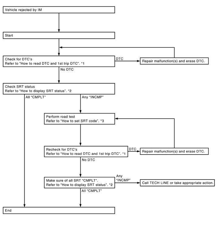
| *1 | “How to Read DTC and 1st Trip DTC” | *2 | “How to Display SRT Status” | *3 | “How to Set SRT Code” |
How to Display SRT StatusWITH CONSULT-IIISelecting “SRT STATUS” in “DTC CONFIRMATION” mode with CONSULT-III.
For items whose SRT codes are set, “CMPLT” is displayed on the CONSULT-III screen; for items whose SRT codes are not set, “INCMP” is displayed.
NOTE:
Though displayed on the CONSULT-III screen, “HO2S HTR” is not SRT item.WITH GSTSelecting Service $01 with GST (Generic Scan Tool)
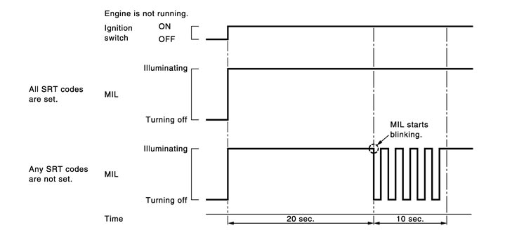
NO TOOLSA SRT code itself cannot be displayed, however SRT status can be.
- 1.Turn ignition switch ON and wait 20 seconds.
- 2.SRT status is indicated as shown below.
- When all SRT codes are set, MIL lights up continuously.
- When any SRT codes are not set, MIL will blink periodically for 10 seconds.
MALFUNCTION INDICATOR LAMP (MIL) DescriptionThe MIL is located on the combination meter.
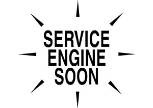
- 1.The MIL will illuminate when the ignition switch is turned ON without the engine running. This is a bulb check.If the MIL does not illuminate, check MIL circuit. Refer to Component Function Check (GT-R certified NISSAN dealer).
- 2.When the engine is started, the MIL should go off.If the MIL remains on, the on board diagnostic system has detected an engine system malfunction.
On Board Diagnostic System FunctionThe on board diagnostic system has the following three functions.
| Diagnostic Test Mode | KEY and ENG. Status | Function | Explanation of Function |
| Mode I | Ignition switch in ON position  Engine stopped  | BULB CHECK | This function checks the MIL bulb for damage (blown, open circuit, etc.). If the MIL does not come on, check MIL circuit. |
Engine running | MALFUNCTION WARNING | When a malfunction is detected twice in two consecutive driving cycles (two trip detection logic), the MIL will illuminate to inform the driver that a malfunction has been detected. The following malfunctions will illuminate or blink the MIL in the 1st trip.
| |
| Mode II | Ignition switch in ON position Engine stopped | SELF-DIAGNOSTIC RESULTS | This function allows DTCs and 1st trip DTCs to be read. |
Diagnostic Test Mode I — Bulb CheckIn this mode, the MIL on the instrument panel should stay ON. If it remains OFF, check MIL circuit. Refer to Component Function Check (GT-R certified NISSAN dealer).
Diagnostic Test Mode I — Malfunction Warning|
MIL |
Condition |
|
ON |
When the malfunction is detected. |
|
OFF |
No malfunction. |
Diagnostic Test Mode II — Self-diagnostic ResultsIn this mode, the DTC and 1st trip DTC are indicated by the number of blinks of the MIL as shown below.
The DTC and 1st trip DTC are displayed at the same time. If the MIL does not illuminate in diagnostic test mode I (Malfunction warning), all displayed items are 1st trip DTCs. If only one code is displayed when the MIL illuminates in diagnostic test mode II (SELF-DIAGNOSTIC RESULTS), it is a DTC; if two or more codes are displayed, they may be either DTCs or 1st trip DTCs. DTC No. is same as that of 1st trip DTC. These unidentified codes can be identified by using the CONSULT-III or GST. A DTC will be used as an example for how to read a code.
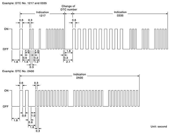
A particular trouble code can be identified by the number of four-digit numeral flashes as per the following.
| Number | 0 | 1 | 2 | 3 | 4 | 5 | 6 | 7 | 8 | 9 | A | B | C | D | E | F |
| Flashes | 10 | 1 | 2 | 3 | 4 | 5 | 6 | 7 | 8 | 9 | 11 | 12 | 13 | 14 | 15 | 16 |
The length of time the 1,000th-digit numeral flashes on and off is 1.2 seconds consisting of an ON (0.6-second) - OFF (0.6-second) cycle.
The 100th-digit numeral and lower digit numerals consist of a 0.3-seconds ON and 0.3-seconds OFF cycle.
A change from one digit numeral to another occurs at an interval of 1.0-second OFF. In other words, the later numeral appears on the display 1.3 seconds after the former numeral has disappeared.
A change from one trouble code to another occurs at an interval of 1.8-seconds OFF.
In this way, all the detected malfunctions are classified by their DTC numbers. The DTC 0000 refers to no malfunction. (See DTC Index)
How to Switch Diagnostic Test ModeNOTE:
-
It is better to count the time accurately with a clock.
-
It is impossible to switch the diagnostic mode when an accelerator pedal position sensor circuit has a malfunction.
-
ECM always returns to Diagnostic Test Mode I after the ignition switch is turned OFF.
HOW TO SET DIAGNOSTIC TEST MODE II (SELF-DIAGNOSTIC RESULTS)
- Confirm that accelerator pedal is fully released, turn ignition switch ON and wait 3 seconds.
- Repeat the following procedure quickly five times within 5 seconds.
- Fully depress the accelerator pedal.
- Fully release the accelerator pedal.
- Wait 7 seconds, fully depress the accelerator pedal and keep it depressed for approx. 10 seconds until the MIL starts blinking.NOTE:Do not release the accelerator pedal for 10 seconds if MIL starts blinking during this period. This blinking is displaying SRT status and is continued for another 10 seconds.
- Fully release the accelerator pedal.ECM has entered to Diagnostic Test Mode II (Self-diagnostic results).NOTE:Wait until the same DTC (or 1st trip DTC) appears to completely confirm all DTCs.
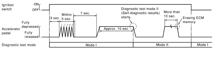
- Set ECM in Diagnostic Test Mode II (Self-diagnostic results). Refer to “How to Set Diagnostic Test Mode II (Self-diagnostic Results)”.
- Fully depress the accelerator pedal and keep it depressed for more than 10 seconds.The emission-related diagnostic information has been erased from the backup memory in the ECM.
- Fully release the accelerator pedal, and confirm the DTC 0000 is displayed.
- If the battery is disconnected, the DTC will be lost from the backup memory within 24 hours.
- Do not erase the stored memory before starting trouble diagnoses.
OBD System Operation Chart Relationship Between MIL, 1st Trip DTC, DTC, and Detectable Items- When a malfunction is detected for the first time, the 1st trip DTC and the 1st trip freeze frame data are stored in the ECM memory.
- When the same malfunction is detected in two consecutive trips, the DTC and the freeze frame data are stored in the ECM memory, and the MIL will come on.
- The MIL will turn off after the vehicle is driven 3 times (driving pattern B) with no malfunction. The drive is counted only when the recorded driving pattern is met (as stored in the ECM). If another malfunction occurs while counting, the counter will reset.
- The DTC and the freeze frame data will be stored until the vehicle is driven 40 times (driving pattern A) without the same malfunction recurring (except for Misfire and Fuel Injection System). For Misfire and Fuel Injection System, the DTC and freeze frame data will be stored until the vehicle is driven 80 times (driving pattern C) without the same malfunction recurring. The “TIME” in “SELF-DIAGNOSTIC RESULTS” mode of CONSULT-III will count the number of times the vehicle is driven.
- The 1st trip DTC is not displayed when the self-diagnosis results in OK for the 2nd trip.
Summary Chart|
Items |
Fuel Injection System |
Misfire |
Other |
|
MIL (turns off) |
3 (pattern B) |
3 (pattern B) |
3 (pattern B) |
|
DTC, Freeze Frame Data (no display) |
80 (pattern C) |
80 (pattern C) |
40 (pattern A) |
|
1st Trip DTC (clear) |
1 (pattern C), *1 |
1 (pattern C), *1 |
1 (pattern B) |
|
1st Trip Freeze Frame Data (clear) |
*1, *2 |
*1, *2 |
1 (pattern B) |
Relationship Between MIL, DTC, 1st Trip DTC and Driving Patterns for “Misfire <Exhaust Quality Deterioration>”, “Fuel Injection System”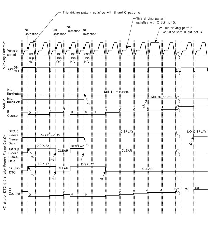
|
*1: |
When the same malfunction is detected in two consecutive trips, MIL will light up. |
*2: |
MIL will turn off after vehicle is driven 3 times (pattern B) without any malfunctions. |
*3: |
When the same malfunction is detected in two consecutive trips, the DTC and the freeze frame data will be stored in ECM. |
|
*4: |
The DTC and the freeze frame data will not be displayed any longer after vehicle is driven 80 times (pattern C) without the same malfunction. (The DTC and the freeze frame data still remain in ECM.) |
*5: |
When a malfunction is detected for the first time, the 1st trip DTC and the 1st trip freeze frame data will be stored in ECM. |
*6: |
The 1st trip DTC and the 1st trip freeze frame data will be cleared at the moment OK is detected. |
|
*7: |
When the same malfunction is detected in the 2nd trip, the 1st trip freeze frame data will be cleared. |
*8: |
1st trip DTC will be cleared when vehicle is driven once (pattern C) without the same malfunction after DTC is stored in ECM. |
|
|
Explanation for Driving Patterns for “Misfire <Exhaust Quality Deterioration>”, “Fuel Injection System”<Driving Pattern B>
Driving pattern B means the vehicle operation as per the following:
All components and systems should be monitored at least once by the OBD system.
- The B counter will be cleared when the malfunction is detected once regardless of the driving pattern.
- The B counter will be counted up when driving pattern B is satisfied without any malfunction.
- The MIL will turn off when the B counter reaches 3. (*2 in “OBD SYSTEM OPERATION CHART”)
Driving pattern C means operating vehicle as per the following:
The following conditions should be satisfied at the same time:
Engine speed: (Engine speed in the freeze frame data) ±375 rpm
Calculated load value: (Calculated load value in the freeze frame data) x (1±0.1) [%]
Engine coolant temperature (T) condition:
- When the freeze frame data shows lower than 70°C (158°F), T should be lower than 70°C (158°F).
- When the freeze frame data shows higher than or equal to 70°C (158°F), T should be higher than or equal to 70°C (158°F).
If the stored freeze frame data is as per the following:
Engine speed: 850 rpm, Calculated load value: 30%, Engine coolant temperature: 80°C (176°F)
To be satisfied with driving pattern C, the vehicle should run under the following conditions:
Engine speed: 475 - 1,225 rpm, Calculated load value: 27 - 33%, Engine coolant temperature: more than 70°C (158°F)
- The C counter will be cleared when the malfunction is detected regardless of vehicle conditions above.
- The C counter will be counted up when vehicle conditions above are satisfied without the same malfunction.
- The DTC will not be displayed after C counter reaches 80.
- The 1st trip DTC will be cleared when C counter is counted once without the same malfunction after DTC is stored in ECM.
Relationship Between MIL, DTC, 1st Trip DTC and Driving Patterns Except For “Misfire <Exhaust Quality Deterioration>”, “Fuel Injection System”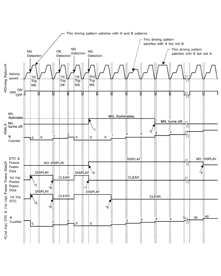
|
*1: |
When the same malfunction is detected in two consecutive trips, MIL will light up. |
*2: |
MIL will turn off after vehicle is driven 3 times (pattern B) without any malfunctions. |
*3: |
When the same malfunction is detected in two consecutive trips, the DTC and the freeze frame data will be stored in ECM. |
|
*4: |
The DTC and the freeze frame data will not be displayed any longer after vehicle is driven 40 times (pattern A) without the same malfunction. (The DTC and the freeze frame data still remain in ECM.) |
*5: |
When a malfunction is detected for the first time, the 1st trip DTC and the 1st trip freeze frame data will be stored in ECM. |
*6: |
1st trip DTC will be cleared after vehicle is driven once (pattern B) without the same malfunction. |
|
*7: |
When the same malfunction is detected in the 2nd trip, the 1st trip freeze frame data will be cleared. |
|
|
|
|
Explanation for Driving Patterns Except for “Misfire <Exhaust Quality Deterioration>”, “Fuel Injection System”<Driving Pattern A>
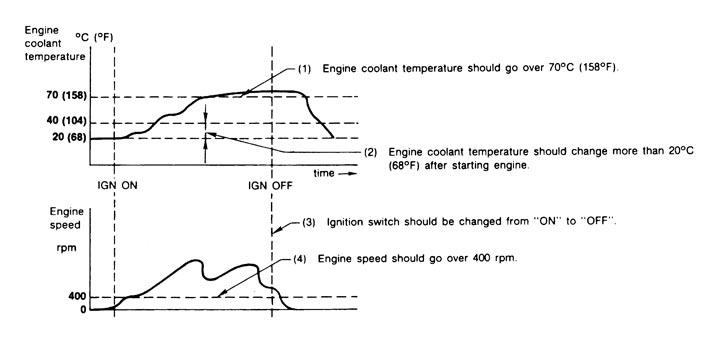
- The A counter will be cleared when the malfunction is detected regardless of (1) - (4).
- The A counter will be counted up when (1) - (4) are satisfied without the same malfunction.
- The DTC will not be displayed after the A counter reaches 40.
Driving pattern B means operating vehicle operation as per the following:
All components and systems should be monitored at least once by the OBD system.
- The B counter will be cleared when the malfunction is detected once regardless of the driving pattern.
- The B counter will be counted up when driving pattern B is satisfied without any malfunctions.
- The MIL will turn off when the B counter reaches 3 (*2 in OBD SYSTEM OPERATION CHART).
CONSULT-III Function
FUNCTION|
Diagnostic test mode |
Function |
|
Work support |
This mode enables a technician to adjust some devices faster and more accurately by following the indications on the CONSULT-III unit. |
|
Self-diagnostic results |
Self-diagnostic results such as 1st trip DTC, DTCs and 1st trip freeze frame data or freeze frame data can be read and erased quickly.* |
|
Data monitor |
Input/Output data in the ECM can be read. |
|
Active test |
Diagnostic Test Mode in which CONSULT-III drives some actuators apart from the ECMs and also shifts some parameters in a specified range. |
|
DTC & SRT confirmation |
The status of system monitoring tests and the self-diagnosis status/results can be confirmed. |
|
Function test |
This mode is used to inform customers when the vehicle requires periodic maintenance. |
|
ECU part number |
ECM part number can be read. |
ENGINE CONTROL COMPONENT PARTS/CONTROL SYSTEMS APPLICATION|
Item
|
DIAGNOSTIC TEST MODE
|
||||||||
|
WORK SUPPORT
|
SELF-DIAGNOSTIC RESULTS
|
DATA MONITOR
|
ACTIVE TEST
|
DTC & SRT
CONFIRMATION |
|||||
|
DTC*1
|
FREEZE FRAME DATA*2
|
SRT STATUS
|
DTC WORK SUPPORT
|
||||||
|
ENGINE CONTROL COMPONENT PARTS
|
INPUT
|
Crankshaft position sensor (POS) |
|
× |
× |
× |
|
|
|
|
Camshaft position sensor (PHASE) |
|
× |
× |
× |
|
|
|
||
|
Mass air flow sensor |
|
× |
|
× |
|
|
|
||
|
Engine coolant temperature sensor |
|
× |
× |
× |
× |
|
|
||
|
Engine oil temperature sensor |
|
× |
|
× |
|
|
|
||
|
Air fuel ratio (A/F) sensor 1 |
|
× |
|
× |
|
× |
× |
||
|
Heated oxygen sensor 2 |
|
× |
|
× |
|
× |
× |
||
|
Vehicle speed signal |
|
× |
× |
× |
|
|
|
||
|
Accelerator pedal position sensor |
|
× |
|
× |
|
|
|
||
|
Throttle position sensor |
|
× |
× |
× |
|
|
|
||
|
Fuel tank temperature sensor |
|
× |
|
× |
× |
|
|
||
|
EVAP control system pressure sensor |
|
× |
|
× |
|
|
|
||
|
Intake air temperature sensor |
|
× |
× |
× |
|
|
|
||
|
Knock sensor |
|
× |
|
|
|
|
|
||
|
Refrigerant pressure sensor |
|
|
|
× |
|
|
|
||
|
Closed throttle position switch (accelerator pedal position sensor signal) |
|
|
|
× |
|
|
|
||
|
Air conditioner switch |
|
|
|
× |
|
|
|
||
|
Park/neutral position (PNP) signal |
|
× |
|
× |
|
|
|
||
|
Stop lamp switch |
|
× |
|
× |
|
|
|
||
|
Power steering pressure sensor |
|
× |
|
× |
|
|
|
||
|
Battery voltage |
|
|
|
× |
|
|
|
||
|
Load signal |
|
|
|
× |
|
|
|
||
|
Turbocharger boost sensor |
|
× |
|
× |
|
|
|
||
|
Fuel level sensor |
|
× |
|
× |
|
|
|
||
|
Secondary air injection system mass air flow sensor |
|
× |
|
× |
|
|
|
||
|
ASCD steering switch |
|
× |
|
× |
|
|
|
||
|
ASCD brake switch |
|
× |
|
× |
|
|
|
||
|
ENGINE CONTROL COMPONENT PARTS
|
OUTPUT
|
Fuel injector |
|
|
|
× |
× |
|
|
|
Fuel pump control module (FPCM) |
|
× |
|
× |
× |
|
|
||
|
Power transistor (Ignition timing) |
|
|
|
× |
× |
|
|
||
|
Throttle control motor relay |
|
× |
|
× |
|
|
|
||
|
Throttle control motor |
|
× |
|
|
|
|
|
||
|
EVAP canister purge volume control solenoid valve |
|
× |
|
× |
× |
|
× |
||
|
Air cut solenoid valve relay |
|
× |
|
× |
|
|
|
||
|
Air pump relay |
|
|
|
× |
|
|
|
||
|
Air conditioner relay |
|
|
|
× |
|
|
|
||
|
Sub fuel pump relay |
|
|
|
× |
× |
|
|
||
|
Cooling fan relay |
|
× |
|
× |
× |
|
|
||
|
Air fuel ratio (A/F) sensor 1 heater |
|
× |
|
× |
|
×*3 |
|
||
|
Heated oxygen sensor 2 heater |
|
× |
|
× |
|
×*3 |
|
||
|
EVAP canister vent control valve |
× |
× |
|
× |
× |
|
|
||
|
Intake valve timing control solenoid valve |
|
× |
|
× |
× |
|
|
||
|
Turbocharger boost control solenoid valve |
|
× |
|
× |
|
|
|
||
|
Calculated load value |
|
|
× |
× |
|
|
|
||
WORK SUPPORT MODE Work Item|
WORK ITEM
|
CONDITION
|
USAGE
|
|
FUEL PRESSURE RELEASE |
|
When releasing fuel pressure from fuel line |
|
IDLE AIR VOL LEARN |
|
When learning the idle air volume |
|
SELF-LEARNING CONT |
|
When clearing mixture ratio self-learning value |
|
EVAP SYSTEM CLOSE |
CLOSE THE EVAP CANISTER VENT CONTROL VALVE IN ORDER TO MAKE EVAP SYSTEM CLOSE UNDER THE FOLLOWING CONDITIONS.
|
When detecting EVAP vapor leak in the EVAP system |
|
VIN REGISTRATION |
|
When registering VIN in ECM |
|
TARGET IDLE RPM ADJ* |
|
When setting target idle speed |
|
TARGET IGN TIM ADJ* |
|
When adjusting target ignition timing |
SELF-DIAG RESULTS MODE Self Diagnostic Item Freeze Frame Data and 1st Trip Freeze Frame Data|
Freeze frame data item* |
Description |
|
DIAG TROUBLE CODE [PXXXX] |
|
|
FUEL SYS-B1 |
|
|
FUEL SYS-B2 |
|
|
CAL/LD VALUE [%] |
|
|
COOLANT TEMP [°C] or [°F] |
|
|
L-FUEL TRM-B1 [%] |
|
|
L-FUEL TRM-B2 [%] |
|
|
S-FUEL TRM-B1 [%] |
|
|
S-FUEL TRM-B2 [%] |
|
|
ENGINE SPEED [rpm] |
|
|
VEHICL SPEED [km/h] or [mph] |
|
|
ABSOL TH·P/S [%] |
|
|
B/FUEL SCHDL [msec] |
|
|
INT/A TEMP SE [°C] or [°F] |
|
|
INT MANI PRES [kPa] |
|
|
COMBUST CONDITION |
DATA MONITOR MODE Monitored Item| Monitored item | Unit | Description | Remarks |
| ENG SPEED | rpm |
|
|
| MAS A/F SE-B1 | V |
|
|
| MAS A/F SE-B2 | |||
| B/FUEL SCHDL | msec |
|
|
| A/F ALPHA-B1 | % |
|
|
| A/F ALPHA-B2 | |||
| COOLAN TEMP/S | °C or °F |
|
|
| A/F SEN1 (B1) | V |
| |
| A/F SEN1 (B2) | |||
| HO2S2 (B1) | V |
| |
| HO2S2 (B2) | |||
| HO2S2 MNTR (B1) | RICH/LEAN |
|
|
| HO2S2 MNTR (B2) | |||
| VHCL SPEED SE | km/h or mph |
| |
| BATTERY VOLT | V |
| |
| ACCEL SEN 1 | V |
|
|
| ACCEL SEN 2 | |||
| TP SEN 1-B1 | V |
|
|
| TP SEN 2-B1 | |||
| FUEL T/TMP SE | °C or °F |
| |
| INT/A TEMP SE | °C or °F |
| |
| EVAP SYS PRES | V |
| |
| FUEL LEVEL SE | V |
| |
| START SIGNAL | ON/OFF |
|
|
| CLSD THL POS | ON/OFF |
| |
| AIR COND SIG | ON/OFF |
| |
| P/N POSI SW | ON/OFF |
| |
| PW/ST SIGNAL | ON/OFF |
| |
| LOAD SIGNAL | ON/OFF |
| |
| IGNITION SW | ON/OFF |
| |
| HEATER FAN SW | ON/OFF |
| |
| BRAKE SW | ON/OFF |
| |
| INJ PULSE-B1 | msec |
|
|
| INJ PULSE-B2 | |||
| IGN TIMING | BTDC |
|
|
| CAL/LD VALUE | % |
| |
| MASS AIRFLOW | g·m/s |
| |
| PURG VOL C/V | % |
| |
| INT/V TIM (B1) | °CA |
| |
| INT/V TIM (B2) | |||
| INT/V SOL (B1) | % |
| |
| INT/V SOL (B2) | |||
| TP SEN 1-B2 | V |
|
|
| TP SEN 2-B2 | |||
| AIR COND RLY | ON/OFF |
| |
| SUB FP RLY | ON/OFF |
| |
| FPCM | LOW/MID/HI |
| |
| VENT CONT/V | ON/OFF |
| |
| THRTL RELAY | ON/OFF |
| |
| AIR/P CNT S/V | ON/OFF |
| |
| AIR PUMP RLY | ON/OFF |
| |
| HO2S2 HTR (B1) | ON/OFF |
| |
| HO2S2 HTR (B2) | |||
| VEHICLE SPEED | km/h or mph |
| |
| IDL A/V LEARN | YET/CMPLT |
| |
| ENG OIL TEMP | °C or °F |
| |
| TRVL AFTER MIL | km or mile |
| |
| A/F S1 HTR (B1) | % |
| |
| A/F S1 HTR (B2) | |||
| AC PRESS SEN | V |
| |
| VHCL SPEED SE | km/h or mph |
| |
| SET VHCL SPD | km/h or mph |
| |
| MAIN SW | ON/OFF |
| |
| CANCEL SW | ON/OFF |
| |
| RESUME/ACC SW | ON/OFF |
| |
| SET SW | ON/OFF |
| |
| BRAKE SW1 | ON/OFF |
| |
| BRAKE SW2 | ON/OFF |
| |
| VHCL SPD CUT | NON/CUT |
| |
| LO SPEED CUT | NON/CUT |
| |
| AT OD MONITOR | ON/OFF |
| |
| AT OD CANCEL | ON/OFF |
| |
| CRUISE LAMP | ON/OFF |
| |
| SET LAMP | ON/OFF |
| |
| A/F ADJ-B1 | — |
| |
| A/F ADJ-B2 | |||
| FAN DUTY | % |
| |
| TURBO BST SEN- B1 | V |
| |
| TURBO BST SEN- B2 | |||
| FUEL PUMP DUTY | % |
| |
| SNDRY MAS A/F SE | % |
| |
| BOOST S/V DUTY | % |
| |
| THRTL ANGLE B1 | deg |
| |
| THRTL ANGLE B2 |
ACTIVE TEST MODE Test Item|
TEST ITEM |
CONDITION |
JUDGMENT |
CHECK ITEM (REMEDY) |
|
FUEL INJECTION |
|
If trouble symptom disappears, see CHECK ITEM. |
|
|
IGNITION TIMING |
|
If trouble symptom disappears, see CHECK ITEM. |
|
|
POWER BALANCE |
|
Engine runs rough or stops. |
|
|
ENG COOLANT TEMP |
|
If trouble symptom disappears, see CHECK ITEM. |
|
|
SUB FUEL PUMP RELAY |
|
Sub fuel pump relay makes the operating sound. |
|
|
PURG VOL CONT/V |
|
Engine speed changes according to the opening percent. |
|
|
FUEL/T TEMP SEN |
|
||
|
VENT CONTROL/V |
|
Solenoid valve makes an operating sound. |
|
|
V/T ASSIGN ANGLE |
|
If trouble symptom disappears, see CHECK ITEM. |
|
|
FPCM |
|
Fuel pump speed changes or stops. |
|
|
FAN DUTY CONTROL* |
|
Cooling fan speed changes. |
|
DTC & SRT CONFIRMATION MODE SRT STATUS Mode SRT WORK SUPPORT ModeThis mode enables a technician to drive a vehicle to set the SRT while monitoring the SRT status.
DTC WORK SUPPORT ModeDiagnosis Tool Function
DESCRIPTIONGeneric Scan Tool (OBD II scan tool) complying with SAE J1978 has 8 different functions explained below.
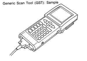
ISO9141 is used as the protocol.
The name “GST” or “Generic Scan Tool” is used in this service manual.
FUNCTION|
Diagnostic Service |
Function |
|
|
Service $01 |
READINESS TESTS |
This diagnostic service gains access to current emission-related data values, including analog inputs and outputs, digital inputs and outputs, and system status information. |
|
Service $02 |
(FREEZE DATA) |
This diagnostic service gains access to emission-related data value that were stored by ECM during the freeze frame. For details, refer to DTC Index. |
|
Service $03 |
DTCs |
This diagnostic service gains access to emission-related power train trouble codes which were stored by ECM. |
|
Service $04 |
CLEAR DIAG INFO |
This diagnostic service can clear all emission-related diagnostic information. This includes:
|
|
Service $06 |
(ON BOARD TESTS) |
This diagnostic service accesses the results of on board diagnostic monitoring tests of specific components/systems that are not continuously monitored. |
|
Service $07 |
(ON BOARD TESTS) |
This diagnostic service enables the off board test drive to obtain test results for emission-related powertrain components/systems that are continuously monitored during normal driving conditions. |
|
Service $08 |
— |
This diagnostic service can close EVAP system in ignition switch ON position (Engine stopped). When this diagnostic service is performed, EVAP canister vent control valve can be closed. In the following conditions, this diagnostic service cannot function.
|
|
Service $09 |
(CALIBRATION ID) |
This diagnostic service enables the off-board test device to request specific vehicle information such as Vehicle Identification Number (VIN) and Calibration IDs. |
INSPECTION PROCEDURE- 1.Turn ignition switch OFF.
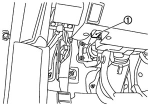
- 2.Connect “GST” to data link connector (1), which is located under LH dash panel near the hood opener handle.
- 3.Turn ignition switch ON.
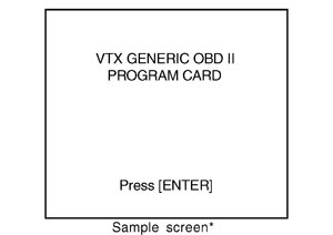
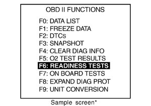
- 4.Enter the program according to instruction on the screen or in the operation manual.(*: Regarding GST screens in this section, sample screens are shown.)
- 5.Perform each diagnostic mode according to each service procedure.
For further information, see the GST Operation Manual of the tool maker.