Nissan GT-R (R35) · Service Manual ENGINE

P0101, P010B MAF SENSOR

VR38

P0101 P010B

Description


The mass air flow sensor (1) is placed in the stream of intake air. It measures the intake flow rate by measuring a part of the entire intake flow. The mass air flow sensor controls the temperature of the hot wire to a certain amount. The heat generated by the hot wire is reduced as the intake air flows around it. The more air, the greater the heat loss.
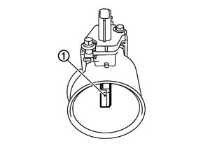
PBIA9559J.JPG
Therefore, the electric current supplied to hot wire is changed to maintain the temperature of the hot wire as air flow increases. The ECM detects the air flow by means of this current change.

DTC Logic

 
 DTC DETECTION LOGIC

DTC No.
Trouble diagnosis name
DTC detecting condition
Possible cause
P0101
Mass air flow sensor (bank 1) circuit range/performance
A)
A high voltage from the sensor is sent to ECM under light load driving condition.
  • Harness or connectors
    (The sensor circuit is open or shorted.)
  • Mass air flow sensor
  • EVAP control system pressure sensor
B)
A low voltage from the sensor is sent to ECM under heavy load driving condition.
  • Harness or connectors
    (The sensor circuit is open or shorted.)
  • Intake air leaks
  • Mass air flow sensor
  • EVAP control system pressure sensor
  • Intake air temperature sensor
P010B
Mass air flow sensor (bank 2) circuit range/performance
A)
A high voltage from the sensor is sent to ECM under light load driving condition.
  • Harness or connectors
    (The sensor circuit is open or shorted.)
  • Mass air flow sensor
  • EVAP control system pressure sensor
B)
A low voltage from the sensor is sent to ECM under heavy load driving condition.
  • Harness or connectors
    (The sensor circuit is open or shorted.)
  • Intake air leaks
  • Mass air flow sensor
  • EVAP control system pressure sensor
  • Intake air temperature sensor

 
 DTC CONFIRMATION PROCEDURE

 
 1.PRECONDITIONING
 
 2.PERFORM DTC CONFIRMATION PROCEDURE FOR MALFUNCTION A
 
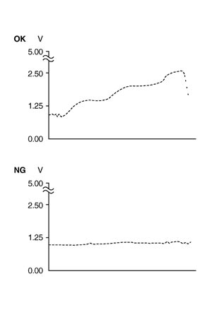
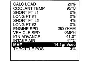
 3.CHECK MASS AIR FLOW SENSOR FUNCTION
 
 4.PERFORM DTC CONFIRMATION PROCEDURE FOR MALFUNCTION B
 
 5.PERFORM COMPONENT FUNCTION CHECK FOR MALFUNCTION B

Component Function Check


 1.PERFORM COMPONENT FUNCTION CHECK FOR MALFUNCTION B

Diagnosis Procedure


 1.INSPECTION START
 
 2.CHECK INTAKE SYSTEM
 
 3.CHECK GROUND CONNECTION
 
 4.CHECK MAF SENSOR POWER SUPPLY CIRCUIT
 
 5.DETECT MALFUNCTIONING PART
 
 6.CHECK MAF SENSOR GROUND CIRCUIT FOR OPEN AND SHORT
 
 7.CHECK MAF SENSOR INPUT SIGNAL CIRCUIT FOR OPEN AND SHORT
 
 8.CHECK INTAKE AIR TEMPERATURE SENSOR
 
 9.CHECK EVAP CONTROL SYSTEM PRESSURE SENSOR
 
 10.CHECK MASS AIR FLOW SENSOR
 
 11.CHECK INTERMITTENT INCIDENT

Component Inspection


 1.CHECK MASS AIR FLOW SENSOR-I
 
 2.CHECK FOR THE CAUSE OF UNEVEN AIR FLOW THROUGH MASS AIR FLOW SENSOR
 
 3.CHECK MASS AIR FLOW SENSOR-II
 
 4.CHECK MASS AIR FLOW SENSOR-III