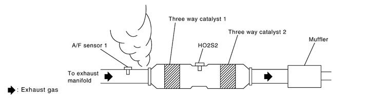
P0133, P0153 A/F SENSOR 1
VR38
P0133 P0153
Description
The air fuel ratio (A/F) sensor 1 is a planar one-cell limit current sensor. The sensor element of the A/F sensor 1 is composed an electrode layer, which transports ions. It has a heater in the element.
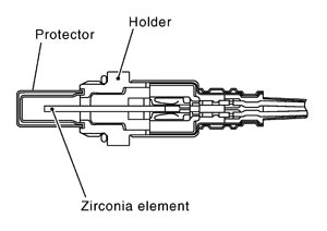
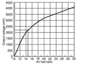
The sensor is capable of precise measurement
 = 1, but also in the lean and rich range. Together with its control electronics, the sensor outputs a clear, continuous signal throughout a wide range.
 The exhaust gas components diffuse through the diffusion layer at the sensor cell. An electrode layer is applied voltage, and this current relative oxygen density in lean. Also this current relative hydrocarbon density in rich.
Therefore, the A/F sensor 1 is able to indicate air fuel ratio by this electrode layer of current. In addition, a heater is integrated in the sensor to ensure the required operating temperature of about 800°C (1,472°F).
DTC Logic
 DTC DETECTION LOGIC
To judge the malfunction of A/F sensor 1, this diagnosis measures response time of the A/F signal computed by ECM from the A/F sensor 1 signal. The time is compensated by engine operating (speed and load), fuel feedback control constant, and the A/F sensor 1 temperature index. Judgment is based on whether the compensated time (the A/F signal cycling time index) is inordinately long or not.
| DTC No. | Trouble diagnosis name | DTC detecting condition | Possible Cause |
| P0133 | Air fuel ratio (A/F) sensor 1 (bank 1) circuit slow response |
|
|
| P0153 | Air fuel ratio (A/F) sensor 1 (bank 2) circuit slow response |
DTC CONFIRMATION PROCEDURE 1.PRECONDITIONING
 With CONSULT-III
 With GST