P0138, P0158 HO2S2
VR38
P0138 P0158
Description
The heated oxygen sensor 2, after three way catalyst 1, monitors the oxygen level in the exhaust gas on each bank.
Even if switching characteristics of the air fuel ratio (A/F) sensor 1 are shifted, the air-fuel ratio is controlled to stoichiometric, by the signal from the heated oxygen sensor 2.
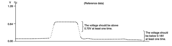
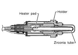
This sensor is made of ceramic zirconia. The zirconia generates voltage from approximately 1 V in richer conditions to 0 V in leaner conditions.
Under normal conditions the heated oxygen sensor 2 is not used for engine control operation.
DTC Logic
 DTC DETECTION LOGIC
The heated oxygen sensor 2 has a much longer switching time between rich and lean than the air fuel ratio (A/F) sensor 1. The oxygen storage capacity of the three way catalyst 1 causes the longer switching time.
MALFUNCTION A
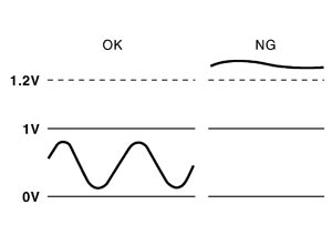
To judge the malfunctions of heated oxygen sensor 2, ECM monitors whether the voltage is unusually high during various driving conditions such as fuelcut.
MALFUNCTION B
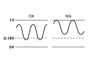
To judge the malfunctions of heated oxygen sensor 2, ECM monitors whether the minimum voltage of sensor is sufficiently low during various driving conditions such as fuelcut.
| DTC No. | Trouble diagnosis name | DTC detecting condition | Possible cause | |
| P0138 | Heated oxygen sensor 2 (bank 1) circuit high voltage | A) | An excessively high voltage from the sensor is sent to ECM. |
|
| B) | The minimum voltage from the sensor does not reach to the specified voltage. |
| ||
| P0158 | Heated oxygen sensor 2 (bank 2) circuit high voltage | A) | An excessively high voltage from the sensor is sent to ECM. |
|
| B) | The minimum voltage from the sensor does not reach to the specified voltage. |
| ||
DTC CONFIRMATION PROCEDURE 1.PRECONDITIONING
 Without CONSULT-III
 With CONSULT-III