Nissan GT-R (R35) · Service Manual ENGINE

P2138 APP SENSOR

VR38

P2138

Description


The accelerator pedal position sensor is installed on the upper end of the accelerator pedal assembly. The sensor detects the accelerator position and sends a signal to the ECM.
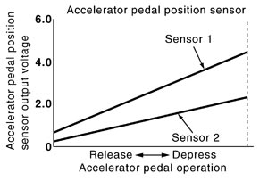
PBIB1741E.JPG
Accelerator pedal position sensor has two sensors. These sensors are a kind of potentiometer which transform the accelerator pedal position into output voltage, and emit the voltage signal to the ECM. In addition, these sensors detect the opening and closing speed of the accelerator pedal and sends voltage signals to the ECM. The ECM judges the current opening angle of the accelerator pedal from these signals and controls the throttle control motor based on these signals.
Idle position of the accelerator pedal is determined by the ECM receiving the signal from the accelerator pedal position sensor. The ECM uses this signal for engine operations such as fuel cut.

DTC Logic

 
 DTC DETECTION LOGIC

NOTE:
If DTC P2138 is displayed with DTC P0643, first perform the trouble diagnosis for DTC P0643. Refer to DTC Logic (GT-R certified NISSAN dealer).

DTC No.
Trouble diagnosis name
DTC detecting condition
Possible cause
P2138
Accelerator pedal position sensor circuit range/performance
Rationally incorrect voltage is sent to ECM compared with the signals from APP sensor 1 and APP sensor 2.
  • Harness or connectors
    (APP sensor 2 circuit is open or shorted.)
    [CKP sensor (POS) circuit is shorted.]
    [CMP sensor (PHASE) (bank 2) circuit is shorted.]
    (Power steering pressure sensor circuit is shorted.)
    (Manifold absolute pressure sensor circuit is shorted.)
    (Refrigerant pressure sensor circuit is shorted.)
  • Accelerator pedal position sensor (APP sensor 2)
  • Crankshaft position sensor (POS)
  • Camshaft position sensor (PHASE) (bank 2)
  • Power steering pressure sensor
  • Manifold absolute pressure sensor
  • Refrigerant pressure sensor

 
 DTC CONFIRMATION PROCEDURE

 
 1.PRECONDITIONING
 
 2.PERFORM DTC CONFIRMATION PROCEDURE

Diagnosis Procedure


 1.CHECK GROUND CONNECTION
 
 2.CHECK APP SENSOR 1 POWER SUPPLY CIRCUIT
 
 3.DETECT MALFUNCTIONING PART
 
 4.CHECK APP SENSOR 2 POWER SUPPLY CIRCUIT-I
 
 5.CHECK APP SENSOR 2 POWER SUPPLY CIRCUIT-II
 
 6.DETECT MALFUNCTIONING PART
 
 7.CHECK SENSOR POWER SUPPLY CIRCUIT
 
 8.CHECK COMPONENTS
 
 9.CHECK APP SENSOR GROUND CIRCUIT FOR OPEN AND SHORT
 
 10.DETECT MALFUNCTIONING PART
 
 11.CHECK APP SENSOR INPUT SIGNAL CIRCUIT FOR OPEN AND SHORT
 
 12.DETECT MALFUNCTIONING PART
 
 13.CHECK APP SENSOR
 
 14.REPLACE ACCELERATOR PEDAL ASSEMBLY
 
 15.CHECK INTERMITTENT INCIDENT

Component Inspection


 1.CHECK ACCELERATOR PEDAL POSITION SENSOR
 
 2.REPLACE ACCELERATOR PEDAL ASSEMBLY

Special Repair Requirement


 1.PERFORM ACCELERATOR PEDAL RELEASED POSITION LEARNING
 
 2.PERFORM THROTTLE VALVE CLOSED POSITION LEARNING
 
 3.PERFORM IDLE AIR VOLUME LEARNING