ECM
VR38
- Reference Value
- Wiring Diagram - ENGINE CONTROL SYSTEM -
- Fail Safe
- DTC Inspection Priority Chart
- DTC Index
- How to Set SRT Code
- Test Value and Test Limit
Reference Value
 VALUES ON THE DIAGNOSIS TOOL
NOTE:
- Specification data are reference values.
- Specification data are output/input values which are detected or supplied by the ECM at the connector.
* Specification data may not be directly related to their components signals/values/operations.
i.e. Adjust ignition timing with a timing light before monitoring IGN TIMING, because the monitor may show the specification data in spite of the ignition timing not being adjusted to the specification data. This IGN TIMING monitors the data calculated by the ECM according to the signals input from the camshaft position sensor and other ignition timing related sensors.
CONSULT-III MONITOR ITEM
|
Monitor Item |
Condition |
Values/Status | |
| ENG SPEED |
| Almost the same speed as the tachometer indication | |
| MAS A/F SE-B1 | See Description (GT-R certified NISSAN dealer). | ||
| MAS A/F SE-B2 | See Description (GT-R certified NISSAN dealer). | ||
| B/FUEL SCHDL | See Description (GT-R certified NISSAN dealer). | ||
| A/F ALPHA-B1 | See Description (GT-R certified NISSAN dealer). | ||
| A/F ALPHA-B2 | See Description (GT-R certified NISSAN dealer). | ||
| COOLAN TEMP/S |
| Indicates engine coolant temperature | |
| A/F SEN1 (B1) |
| Maintaining engine speed at 2,000 rpm | Fluctuates around 2.2 V |
| A/F SEN1 (B2) |
| Maintaining engine speed at 2,000 rpm | Fluctuates around 2.2 V |
| HO2S2 (B1) |
| 0 - 0.3 V ←→ Approx. 0.6 - 1.0 V | |
| HO2S2 (B2) |
| 0 - 0.3 V ←→ Approx. 0.6 - 1.0 V | |
| HO2S2 MNTR (B1) |
| LEAN ←→ RICH | |
| HO2S2 MNTR (B2) |
| LEAN ←→ RICH | |
| VHCL SPEED SE |
| Almost the same speed as speedometer indication | |
| BATTERY VOLT |
| 11 - 14 V | |
| ACCEL SEN 1 |
| Accelerator pedal: Fully released | 0.5 - 1.0 V |
| Accelerator pedal: Fully depressed | 4.2 - 4.8 V | ||
| ACCEL SEN 2* |
| Accelerator pedal: Fully released | 0.5 - 1.0 V |
| Accelerator pedal: Fully depressed | 4.2 - 4.8 V | ||
| TP SEN 1-B1 |
| Accelerator pedal: Fully released | More than 0.36 V |
| Accelerator pedal: Fully depressed | Less than 4.75 V | ||
| TP SEN 2-B1* |
| Accelerator pedal: Fully released | More than 0.36 V |
| Accelerator pedal: Fully depressed | Less than 4.75 V | ||
| FUEL T/TMP SE |
| Indicates fuel tank temperature | |
| INT/A TEMP SE |
| Indicates intake air temperature | |
| EVAP SYS PRES |
| Approx. 1.8 - 4.8 V | |
| FUEL LEVEL SE |
| Depending on fuel level of fuel tank | |
| START SIGNAL |
| OFF → ON → OFF | |
| CLSD THL POS |
| Accelerator pedal: Fully released | ON |
| Accelerator pedal: Slightly depressed | OFF | ||
| AIR COND SIG |
| Air conditioner switch: OFF | OFF |
| Air conditioner switch: ON (Compressor operates.) | ON | ||
| P/N POSI SW |
| Shift lever: P or N | ON |
| Shift lever: Except above | OFF | ||
| PW/ST SIGNAL |
| Steering wheel: Not being turned | OFF |
| Steering wheel: Being turned | ON | ||
| LOAD SIGNAL |
| Rear window defogger switch: ON and/or Lighting switch: 2nd position | ON |
| Rear window defogger switch and lighting switch: OFF | OFF | ||
| IGNITION SW |
| ON → OFF → ON | |
| HEATER FAN SW |
| Heater fan switch: ON | ON |
| Heater fan switch: OFF | OFF | ||
| BRAKE SW |
| Brake pedal: Fully released | OFF |
| Brake pedal: Slightly depressed | ON | ||
| INJ PULSE-B1 |
| Idle | 1.4 - 2.4 msec |
| 2,000 rpm | 1.4 - 2.4 msec | ||
| INJ PULSE-B2 |
| Idle | 1.4 - 2.4 msec |
| 2,000 rpm | 1.4 - 2.4 msec | ||
| IGN TIMING |
| Idle | 7° - 11° BTDC |
| 2,000 rpm | 7° - 11° BTDC | ||
| CAL/LD VALUE |
| Idle | 5% - 35% |
| 2,500 rpm | 5% - 35% | ||
| MASS AIRFLOW |
| Idle | 2.0 - 6.0 g·m/s |
| 2,500 rpm | 7.0 - 20.0 g·m/s | ||
| PURG VOL C/V |
| Idle (Accelerator pedal: Not depressed even slightly, after engine starting.) | 0% |
| 2,000 rpm | — | ||
| INT/V TIM (B1) |
| Idle | −5° - 5°CA |
| 2,000 rpm | Approx. 0° - 30°CA | ||
| INT/V TIM (B2) |
| Idle | −5° - 5°CA |
| 2,000 rpm | Approx. 0° - 30°CA | ||
| INT/V SOL (B1) |
| Idle | 0% - 2% |
| 2,000 rpm | Approx. 0% - 50% | ||
| INT/V SOL (B2) |
| Idle | 0% - 2% |
| 2,000 rpm | Approx. 0% - 50% | ||
| TP SEN 1-B2 |
| Accelerator pedal: Fully released | More than 0.36 V |
| Accelerator pedal: Fully depressed | Less than 4.75 V | ||
| TP SEN 2-B2* |
| Accelerator pedal: Fully released | More than 0.36 V |
| Accelerator pedal: Fully depressed | Less than 4.75 V | ||
| AIR COND RLY |
| Air conditioner switch: OFF | OFF |
| Air conditioner switch: ON (Compressor operates) | ON | ||
| VENT CONT/V |
| OFF | |
| SUB FP RLY |
| Sub fuel pump not operates | OFF |
| Sub fuel pump operates | ON | ||
| FPCM |
| HI | |
| LOW | ||
| THRTL RELAY |
| ON | |
| AIR/P CNT S/V |
| Idle (Secondary air injection system not operates) | OFF |
| Idle (Secondary air injection system operates) | ON | ||
| AIR PUMP RLY |
| Idle (Secondary air injection system not operates) | OFF |
| Idle (Secondary air injection system operates) | ON | ||
| HO2S2 HTR (B1) |
| ON | |
| OFF | ||
| HO2S2 HTR (B2) |
| ON | |
| OFF | ||
| VEHICLE SPEED |
| Almost the same speed as the speedometer indication | |
| IDL A/V LEARN |
| Idle air volume learning has not been performed yet. | YET |
| Idle air volume learning has already been performed successfully. | CMPLT | ||
| SNOW MODE SW |
| Snow mode switch: ON | ON |
| Snow mode switch: OFF | OFF | ||
| ENG OIL TEMP |
| More than 70°C (158°F) | |
| TRVL AFTER MIL |
| Vehicle has traveled after MIL has illuminated. | 0 - 65,535 km (0 - 40,723 miles) |
| A/F S1 HTR (B1) |
| 4 - 100% | |
| A/F S1 HTR (B2) |
| 4 - 100% | |
| AC PRESS SEN |
| 1.0 - 4.0 V | |
| VHCL SPEED SE |
| Almost the same speed as the speedometer indication | |
| SET VHCL SPD |
| ASCD: Operating | The preset vehicle speed is displayed |
| MAIN SW |
| MAIN switch: Pressed | ON |
| MAIN switch: Released | OFF | ||
| CANCEL SW |
| CANCEL switch: Pressed | ON |
| CANCEL switch: Released | OFF | ||
| RESUME/ACC SW |
| RESUME/ACCELERATE switch: Pressed | ON |
| RESUME/ACCELERATE switch: Released | OFF | ||
| SET SW |
| SET/COAST switch: Pressed | ON |
| SET/COAST switch: Released | OFF | ||
| BRAKE SW1 (ASCD brake switch) |
| Brake pedal: Fully released | ON |
| Brake pedal: Slightly depressed | OFF | ||
| BRAKE SW2 (Stop lamp switch) |
| Brake pedal: Fully released | OFF |
| Brake pedal: Slightly depressed | ON | ||
| VHCL SPD CUT |
| NON | |
| LO SPEED CUT |
| NON | |
| AT OD MONITOR |
| OFF | |
| AT OD CANCEL |
| OFF | |
| CRUISE LAMP |
| MAIN switch: Pressed at the 1st time → at the 2nd time | ON → OFF |
| SET LAMP |
| ASCD: Operating | ON |
| ASCD: Not operating | OFF | ||
| A/F ADJ-B1 |
| −0.330 - 0.330 | |
| A/F ADJ-B2 |
| −0.330 - 0.330 | |
| FAN DUTY |
| 0 - 100% | |
| TURBO BST SEN-B1 |
| Same as the ambient pressure | |
|
| 3.07 - 3.15 V | |
|
| 2.91 - 2.99 V | |
| TURBO BST SEN-B2 |
| Same as the ambient pressure | |
|
| 3.07 - 3.15 V | |
|
| 2.91 - 2.99 V | |
| FUEL PUMP DUTY |
| Engine speed: Idle | 30 - 40% |
| SNDRY MAS A/F SE |
| Idle (Secondary air injection system not operates) | 1 L/min |
| Idle (Secondary air injection system operates) | 400 - 550 L/min | ||
| BOOST S/V DUTY |
| 0% | |
|
| 100% | |
| 30 - 60% | ||
| THRTL ANGLE B1 |
| Engine speed: Idle | 1.5 - 3.0 deg |
| THRTL ANGLE B2 |
| Engine speed: Idle | 1.5 - 3.0 deg |
TERMINAL LAYOUT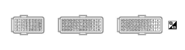 PHYSICAL VALUES
NOTE:
- ECM is located behind the instrument assist lower panel. For this inspection, remove passenger side instrument lower panel.
- Specification data are reference values and are measured between each terminal and ground.
- Pulse signal is measured by CONSULT-III.
|
Terminal No. (Wire color) |
Description |
Condition |
Value (Approx.) |
||
|
+ |
‐– |
Signal name |
Input/Output |
||
|
1 (Y) |
128 (B) |
Throttle control motor relay power supply (bank 2) |
Input |
[Ignition switch: ON] |
BATTERY VOLTAGE (11 - 14 V) |
|
2 (G) |
128 (B) |
Throttle control motor (Open) (bank 2) |
Output |
[Ignition switch: ON]
|
0 - 14 V 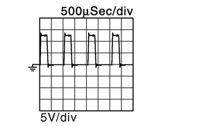 |
[Ignition switch: ON]
|
0 - 14 V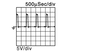 |
||||
|
3 (O) |
128 (B) |
A/F sensor 1 heater (bank 2) |
Output |
[Engine is running]
|
2.9 - 8.8 V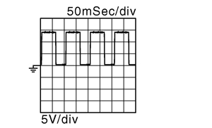 |
|
4 (LG) |
128 (B) |
A/F sensor 1 heater (bank 1) |
Output |
[Engine is running]
|
2.9 - 8.8 V |
|
5 (L) |
128 (B) |
Throttle control motor (Close) (bank 2) |
Output |
[Ignition switch: ON]
|
0 - 14 V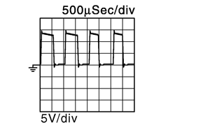 |
|
6 (B) |
— |
ECM ground |
— |
— |
— |
|
7 (L) |
128 (B) |
EVAP canister vent control valve |
Output |
[Ignition switch: ON] |
BATTERY VOLTAGE (11 - 14 V) |
|
8 (V) |
128 (B) |
EVAP canister purge volume control solenoid valve |
Output |
[Engine is running]
|
BATTERY VOLTAGE (11 - 14 V) 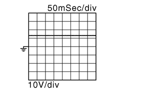 |
[Engine is running]
|
BATTERY VOLTAGE (11 - 14 V) 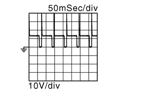 |
||||
|
9 (G) |
128 (B) |
Ignition signal No. 2 |
Output |
[Engine is running]
|
0 - 0.2 V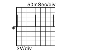 |
|
10 (Y) |
Ignition signal No. 1 |
||||
|
13 (L) |
Ignition signal No. 3 |
||||
|
33 (R) |
Ignition signal No. 4 |
[Engine is running]
|
0.1 - 0.4 V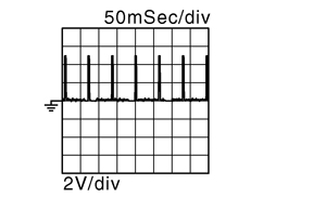 |
||
|
34 (V) |
Ignition signal No. 5 |
||||
|
38 (GR) |
Ignition signal No. 6 |
||||
|
15 (B) |
— |
Sensor ground [Throttle position sensor (bank 2)] |
— |
— |
— |
|
17 (LG) |
128 (B) |
Fuel injector No. 3 |
Output |
[Engine is running]
|
BATTERY VOLTAGE (11 - 14 V) 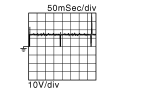 |
|
21 (Y) |
Fuel injector No. 2 |
||||
|
25 (P) |
Fuel injector No. 1 |
||||
|
37 (SB) |
Fuel injector No. 4 |
[Engine is running]
|
BATTERY VOLTAGE (11 - 14 V) 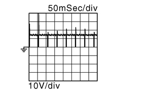 |
||
|
41 (G) |
Fuel injector No. 5 |
||||
|
45 (R) |
Fuel injector No. 6 |
||||
|
19 (GR) |
— |
Sensor ground [Mass air flow sensor (bank 2)] |
— |
— |
— |
|
20 (G) |
— |
Sensor ground [Throttle position sensor (bank 1)] |
— |
— |
— |
|
22 (W) |
— |
Sensor ground [Mass air flow sensor (bank 1), Intake air temperature sensor (bank 1)] |
— |
— |
— |
|
23 (V) |
— |
Sensor ground (Secondary air injection system mass air flow sensor) |
— |
— |
— |
|
24 (LG) |
23 (V) |
Secondary air injection system mass air flow sensor |
Input |
[Ignition switch: ON]
|
0.15 - 0.4 V |
[Engine is running]
|
3 - 3.8 V |
||||
|
26 (O) |
— |
Sensor ground (Engine coolant temperature sensor, Engine oil temperature sensor, Fuel tank temperature sensor) |
— |
— |
— |
|
27 (L) |
26 (O) |
Engine oil temperature sensor |
Input |
[Engine is running] |
0 - 4.8 V Output voltage varies with engine oil temperature. |
|
28 (W) |
15 (B) |
Throttle position sensor 1 (bank 2) |
Input |
[Ignition switch: ON]
|
More than 0.36 V |
[Ignition switch: ON]
|
Less than 4.75 V |
||||
|
29 (LG) |
128 (B) |
Fuel pump control module (FPCM) |
Output |
[When cranking engine] |
4.1 V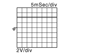 |
[Engine is running]
|
1.4 V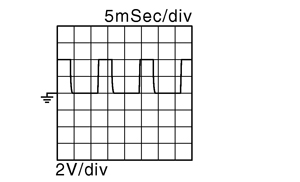 |
||||
|
30 (G) |
128 (B) |
Fuel pump control model (FPCM) check |
Input |
[Engine is running]
|
BATTERY VOLTAGE (11 - 14 V) |
|
31 (BR) |
19 (GR) |
Mass air flow sensor (bank 2) |
Input |
[Engine is running]
|
0.9 - 1.2 V |
[Engine is running]
|
1.4 - 1.8 V |
||||
|
32 (R) |
15 (B) |
Throttle position sensor 2 (bank 2) |
Input |
[Ignition switch: ON]
|
Less than 4.75 V |
[Ignition switch: ON]
|
More than 0.36 V |
||||
|
36 (Y) |
20 (G) |
Throttle position sensor 2 (bank 1) |
Input |
[Ignition switch: ON]
|
Less than 4.75 V |
[Ignition switch: ON]
|
More than 0.36 V |
||||
|
40 (L) |
20 (G) |
Throttle position sensor 1 (bank 1) |
Input |
[Ignition switch: ON]
|
More than 0.36 V |
[Ignition switch: ON]
|
Less than 4.75 V |
||||
|
42 (W) |
26 (O) |
Fuel tank temperature sensor |
Input |
[Engine is running] |
0 - 4.8 V Output voltage varies with fuel tank temperature. |
|
44 (P) |
22 (W) |
Intake air temperature sensor (bank 1) |
Input |
[Engine is running] |
0 - 4.8 V Output voltage varies with intake air temperature. |
|
46 (Y) |
26 (O) |
Engine coolant temperature sensor |
Input |
[Engine is running] |
0 - 4.8 V Output voltage varies with engine coolant temperature. |
|
47 (O) |
22 (W) |
Mass air flow sensor (bank 1) |
Input |
[Engine is running]
|
0.9 - 1.2 V |
[Engine is running]
|
1.4 - 1.8 V |
||||
|
48 (G) |
74 (R) |
Manifold absolute pressure (MAP) sensor |
Input |
[Engine is running]
|
0.9V |
[Engine is running]
|
1.6 - 2.0 V |
||||
|
49 (Y) |
128 (B) |
Throttle control motor relay power supply (bank 1) |
Input |
[Ignition switch: ON] |
BATTERY VOLTAGE (11 - 14 V) |
|
50 (SB) |
128 (B) |
Throttle control motor (Open) (bank 1) |
Output |
[Ignition switch: ON]
|
0 - 14 V |
[Ignition switch: ON]
|
0 - 14 V |
||||
|
51 (G) |
128 (B) |
Intake valve timing control solenoid valve (bank 2) |
Output |
[Engine is running]
|
BATTERY VOLTAGE (11 - 14V) |
[Engine is running]
|
7 - 12 V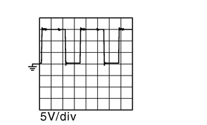 |
||||
|
52 (L) |
128 (B) |
Intake valve timing control solenoid valve (bank 1) |
Output |
[Engine is running]
|
BATTERY VOLTAGE (11 - 14 V) |
[Engine is running]
|
7 - 12 V |
||||
|
53 (BR) |
128 (B) |
Throttle control motor (Close) (bank 1) |
Output |
[Ignition switch: ON]
|
0 - 14 V |
|
54 (B) |
— |
ECM ground |
— |
— |
— |
|
55 (R) |
128 (B) |
Heated oxygen sensor 2 heater (bank 1) |
Output |
[Engine is running]
|
0 - 14 V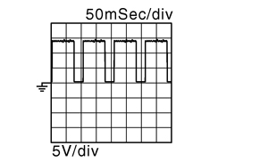 |
[Ignition switch: ON]
|
BATTERY VOLTAGE (11 - 14 V) |
||||
|
56 (W) |
128 (B) |
Heated oxygen sensor 2 heater (bank 2) |
Output |
[Engine is running]
|
0 - 14 V |
[Ignition switch: ON]
|
BATTERY VOLTAGE (11 - 14 V) |
||||
|
61 (GR) |
128 (B) |
Turbocharger boost control solenoid valve |
Output |
[Engine is running]
|
BATTERY VOLTAGE (11 - 14 V) |
[Engine is running]
|
0.35 V |
||||
|
62 (B) |
— |
Sensor ground [Camshaft position sensor (PHASE) (bank 1)] |
— |
— |
— |
|
63 (O) |
128 (B) |
Camshaft position sensor (PHASE) (bank 1) |
Input |
[Engine is running]
|
3.0 - 5.0 V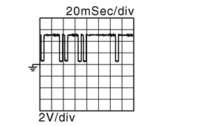 |
[Engine is running]
|
3.0 - 5.0 V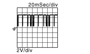 |
||||
|
64 (BR) |
128 (B) |
Crankshaft position sensor (POS) |
Input |
[Engine is running]
|
4.0 - 5.0 V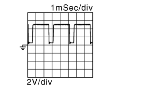 |
[Engine is running]
|
4.0 - 5.0 V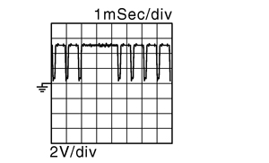 |
||||
|
66 (V) |
— |
Sensor ground [Camshaft position sensor (PHASE) (bank 2)] |
— |
— |
— |
|
67 (Y) |
128 (B) |
Camshaft position sensor (PHASE) (bank 2) |
Input |
[Engine is running]
|
3.0 - 5.0 V |
[Engine is running]
|
3.0 - 5.0 V |
||||
|
68 (B) |
— |
Sensor ground [Crankshaft position sensor (POS)] |
— |
— |
— |
|
70 (SB) |
— |
Sensor ground [Heated oxygen sensor 2] |
— |
— |
— |
|
71 (—) |
— |
Sensor ground (Knock sensor) |
— |
— |
— |
|
72 (W) |
71 (—) |
Knock sensor (bank 1) |
Input |
[Engine is running]
|
2.5 V* |
|
73 (W) |
70 (SB) |
Heated oxygen sensor 2 (bank 1) |
Input |
[Engine is running]
|
0 - 1.0 V |
|
74 (R) |
— |
Sensor ground (Refrigerant pressure sensor, Power steering pressure sensor, ASCD steering switch) |
— |
— |
— |
|
75 (P) |
— |
Sensor ground (Turbocharger boost sensor, EVAP control system pressure sensor) |
— |
— |
— |
|
76 (W) |
71 (—) |
Knock sensor (bank 2) |
Input |
[Engine is running]
|
2.5 V* |
|
77 (GR) |
70 (SB) |
Heated oxygen sensor 2 (bank 2) |
Input |
[Engine is running]
|
0 - 1.0 V |
|
78 (LG) |
75 (P) |
EVAP control system pressure sensor |
Input |
[Ignition switch: ON] |
1.8 - 4.8 V |
|
79 (L) |
75 (P) |
Turbocharger boost sensor (bank 2) |
Input |
[Engine is running]
|
1.98 V |
[Engine is running]
|
2.0 V |
||||
|
80 (L) |
75 (P) |
Turbocharger boost sensor (bank 1) |
Input |
[Engine is running]
|
1.98 V |
[Engine is running]
|
2.0 V |
||||
|
81 (O) |
128 (B) |
A/F sensor 1 (bank 1) |
Input |
[Ignition switch: ON] |
2.2 V |
|
82 (V) |
128 (B) |
A/F sensor 1 (bank 1) |
Input |
[Engine is running]
|
1.8 V Output voltage varies with air fuel ratio. |
|
83 (G) |
74 (R) |
Power steering pressure sensor |
Output |
[Engine is running]
|
0.5 - 4.5 V |
[Engine is running]
|
0.4 - 0.8 V |
||||
|
84 (SB) |
15 (B) |
Sensor power supply [Throttle position sensor (bank 2)] |
— |
[Ignition switch: ON] |
5 V |
|
85 (BR) |
128 (B) |
A/F sensor 1 (bank 2) |
Input |
[Ignition switch: ON] |
2.2 V |
|
86 (Y) |
128 (B) |
A/F sensor 1 (bank 2) |
Input |
[Engine is running]
|
1.8 V Output voltage varies with air fuel ratio. |
|
87 (W) |
128 (B) |
Sensor power supply [Crankshaft position sensor (POS)] |
— |
[Ignition switch: ON] |
5 V |
|
88 (L) |
128 (B) |
Sensor power supply [Camshaft position sensor (PHASE) (bank 1)] |
— |
[Ignition switch: ON] |
5 V |
|
89 (L) |
74 (R) |
Refrigerant pressure sensor |
Input |
[Engine is running]
|
1.0 - 4.0 V |
|
91 (P) |
128 (B) |
Sensor power supply [Camshaft position sensor (PHASE) (bank 2)] |
— |
[Ignition switch: ON] |
5 V |
|
92 (R) |
75 (P) |
Sensor power supply [Turbocharger boost sensor, EVAP control system pressure sensor] |
— |
[Ignition switch: ON] |
5 V |
|
93 (GR) |
128 (B) |
Sub fuel pump (+) |
Input |
[Engine is running]
|
0 V |
[Engine is running]
|
BATTERY VOLTAGE (11 - 14 V) |
||||
|
94 (SB) |
128 (B) |
Sub fuel pump (-) |
Input |
[Engine is running]
|
0 V |
[Engine is running]
|
0 V |
||||
|
95 (Y) |
74 (R) |
Sensor power supply (Refrigerant pressure sensor, Power steering pressure sensor, Manifold absolute pressure sensor) |
— |
[Ignition switch: ON] |
5 V |
|
96 (V) |
20 (G) |
Sensor power supply [Throttle position sensor (bank 1)] |
— |
[Ignition switch: ON] |
5 V |
|
97 (P) |
— |
CAN communication line |
Input/Output |
— |
— |
|
99 (SB) |
107 (O) |
Sensor power supply (Accelerator pedal position sensor 2) |
— |
[Ignition switch: ON] |
5 V |
|
100 (BR) |
103 (GR) |
Sensor power supply (Accelerator pedal position sensor 1) |
— |
[Ignition switch: ON] |
5 V |
|
101 (L) |
— |
CAN communication line |
Input/Output |
— |
— |
|
102 (G) |
74 (R) |
ASCD steering switch |
Input |
[Ignition switch: ON]
|
4.0 - 4.2 V |
[Ignition switch: ON]
|
0 V |
||||
[Ignition switch: ON]
|
0.9 - 1.5 V |
||||
[Ignition switch: ON]
|
3.0 - 3.3 V |
||||
[Ignition switch: ON]
|
1.9 - 2.4 V |
||||
|
103 (GR) |
— |
Sensor ground (Accelerator pedal position sensor 1) |
— |
— |
— |
|
104 (P) |
103 (GR) |
Accelerator pedal position sensor 1 |
Input |
[Ignition switch: ON]
|
0.5 - 1.0 V |
[Ignition switch: ON]
|
4.2 - 4.8 V |
||||
|
105 (W) |
128 (B) |
ECM relay (Self shut-off) |
Output |
[Engine is running] [Ignition switch: OFF]
|
0 - 1.5 V |
[Ignition switch: OFF]
|
BATTERY VOLTAGE (11 - 14 V) |
||||
|
106 (LG) |
128 (B) |
Ignition switch |
Input |
[Ignition switch: OFF] |
0V |
|
[Ignition switch: ON] |
BATTERY VOLTAGE (11 - 14 V) |
||||
|
107 (O) |
— |
Sensor ground (Accelerator pedal position sensor 2) |
— |
— |
— |
|
108 (L) |
107 (O) |
Accelerator pedal position sensor 2 |
Input |
[Ignition switch: ON]
|
0.25 - 0.50 V |
[Ignition switch: ON]
|
2.0 - 2.5 V |
||||
|
109 (L) |
128 (B) |
Air cut solenoid valve relay |
Output |
[Engine is running]
|
BATTERY VOLTAGE (11 - 14 V) |
[Engine is running]
|
0 V |
||||
|
110 (P) |
128 (B) |
Stop lamp switch |
Input |
[Ignition switch: OFF]
|
0 V |
[Ignition switch: OFF]
|
BATTERY VOLTAGE (11 - 14 V) |
||||
|
111 (GR) |
128 (B) |
PNP signal |
Input |
[Ignition switch: ON]
|
BATTERY VOLTAGE (11 - 14 V) |
[Ignition switch: ON]
|
0 V |
||||
|
113 (SB) |
128 (B) |
Engine speed signal output |
Output |
[Engine is running]
|
1 V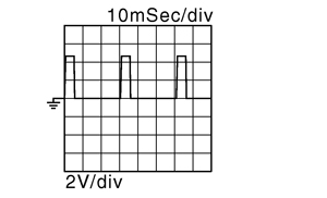 |
[Engine is running]
|
1 V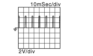 |
||||
|
114 (V) |
128 (B) |
Data link connector |
Input/Output |
[Ignition switch: ON]
|
5 - 14 V |
|
117 (R) |
128 (B) |
ASCD brake switch |
Input |
[Ignition switch: ON]
|
0 V |
[Ignition switch: ON]
|
BATTERY VOLTAGE (11 - 14 V) |
||||
|
118 (W) |
128 (B) |
Power supply for ECM (Back-up) |
Input |
[Ignition switch: OFF] |
BATTERY VOLTAGE (11 - 14 V) |
|
120 (BR) |
128 (B) |
Air pump relay |
Output |
[Engine is running]
|
BATTERY VOLTAGE (11 - 14 V) |
[Engine is running]
|
0 V |
||||
|
121 (P) 122 (V) |
128 (B) |
Power supply for ECM |
Input |
[Ignition switch: ON] |
BATTERY VOLTAGE (11 - 14 V) |
|
124 (B) |
— |
ECM ground |
— |
— |
— |
|
126 (L) |
128 (B) |
Sub fuel pump relay |
Output |
[Engine is running]
|
BATTERY VOLTAGE (11 - 14 V) |
[Engine is running]
|
0 V |
||||
|
127 (G) |
128 (B) |
Throttle control motor relay |
Output |
[Ignition switch: ON → OFF] |
0 - 1.0 V ↓ BATTERY VOLTAGE (11 - 14 V) ↓ 0 V |
|
[Ignition switch: ON] |
0 - 1.0 V |
||||
|
128 (B) |
— |
ECM ground |
— |
— |
— |
Wiring Diagram - ENGINE CONTROL SYSTEM -
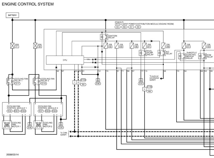
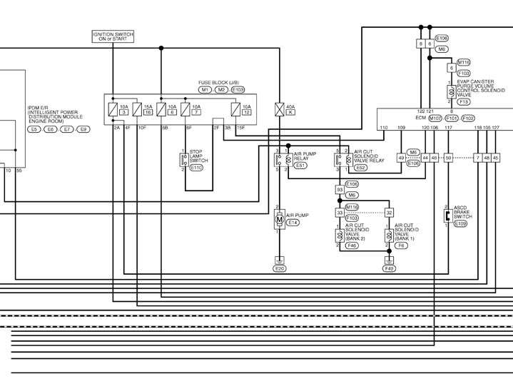
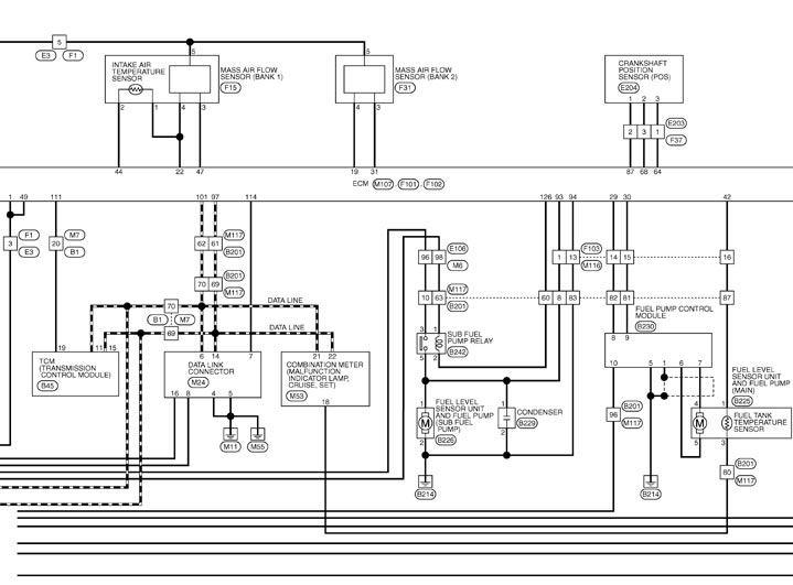
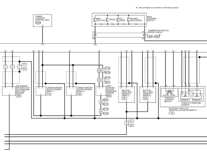
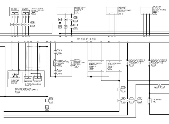
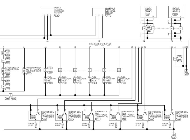
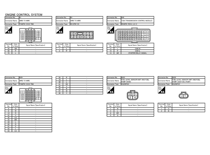
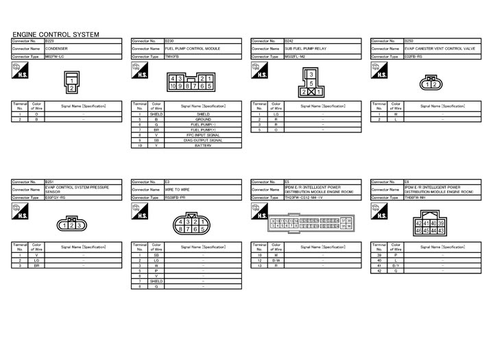
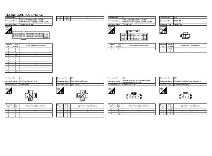
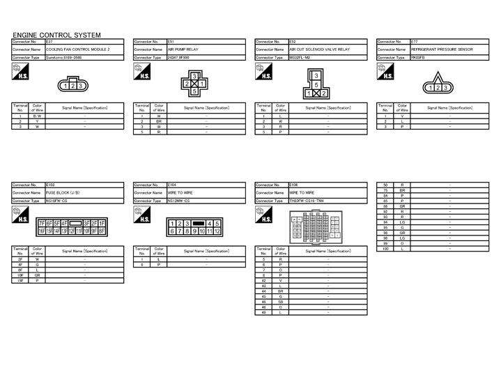
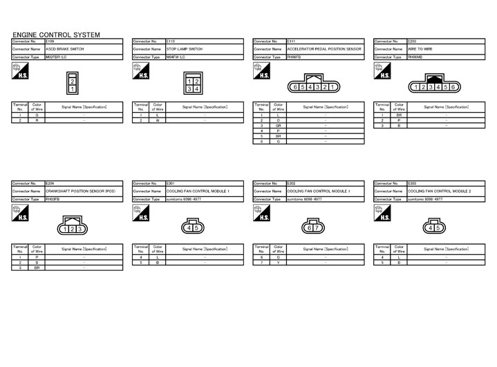
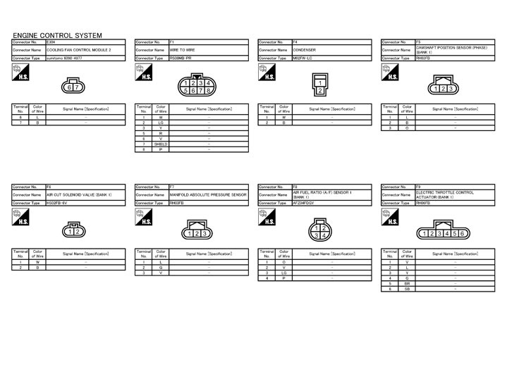
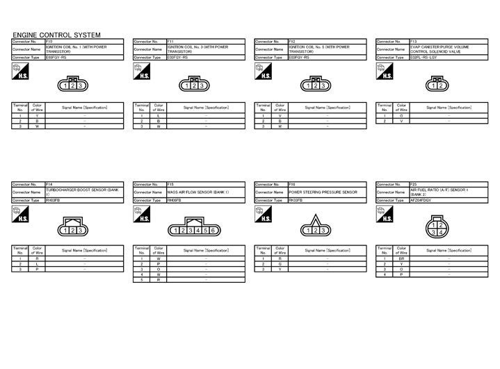
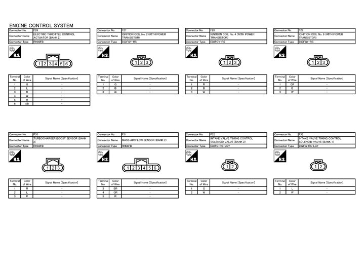
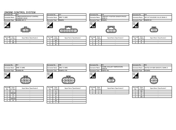
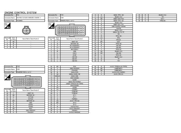
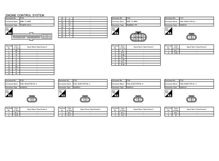
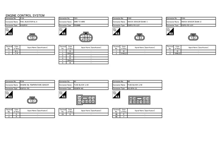
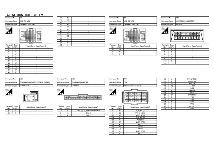
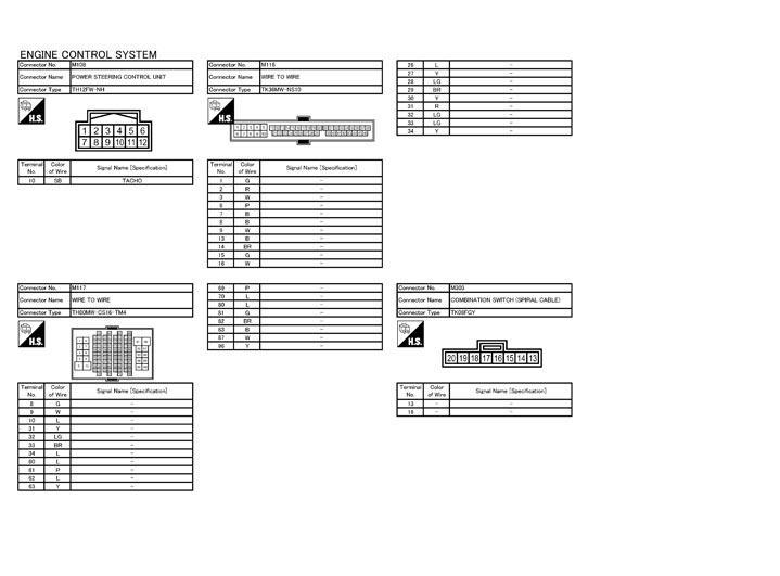
Fail Safe
NON DTC RELATED ITEM|
Engine operating condition in fail-safe mode |
Detected items |
Remarks |
Reference page |
|
Engine speed will not rise more than 2,500 rpm due to the fuel cut |
Malfunction indicator lamp circuit |
When there is an open circuit on MIL circuit, the ECM cannot warn the driver by lighting up MIL when there is malfunction on engine control system. Therefore, when electrical controlled throttle and part of ECM related diagnoses are continuously detected as NG for 5 trips, ECM warns the driver that engine control system malfunctions and MIL circuit is open by means of operating fail-safe function. The fail-safe function also operates when above diagnoses except MIL circuit are detected and demands the driver to repair the malfunction. |
Component Function Check (GT-R certified NISSAN dealer)
|
DTC RELATED ITEM|
DTC No. |
Detected items |
Engine operating condition in fail-safe mode |
|
|
P0011 P0021 |
Intake valve timing control |
The signal is not energized to the intake valve timing control solenoid valve and the valve control does not function. |
|
|
P004A P004D |
Turbocharger boost control solenoid valve |
Sets the duty ratio of the turbocharger boost control solenoid valve to 0%, and decreases the boost to the lower limit. |
|
|
P004C |
The ECM controls the electric throttle control actuator and restricts the torque. |
||
|
P0102 P0103 P010C P010D |
Mass air flow sensor circuit |
Engine speed will not rise more than 2,400 rpm due to the fuel cut. |
|
|
P0117 P0118 |
Engine coolant temperature sensor circuit |
Engine coolant temperature will be determined by ECM based on the following condition. CONSULT-III displays the engine coolant temperature decided by ECM. |
|
|
Condition |
Engine coolant temperature decided (CONSULT-III display) |
||
|
Just as ignition switch is turned ON or START |
40°C (104°F) |
||
|
Approx. 4 minutes or more after engine starting |
80°C (176°F) |
||
|
Except as shown above |
40 - 80°C (104 - 176°F) (Depends on the time) |
||
|
When the fail-safe system for engine coolant temperature sensor is activated, the cooling fan operates while engine is running. |
|||
|
P0122 P0123 P0222 P0223 P0227 P0228 P1239 P2132 P2133 P2135 |
Throttle position sensor |
The ECM controls the electric throttle control actuator in regulating the throttle opening in order for the idle position to be within +10 degrees. The ECM regulates the opening speed of the throttle valve to be slower than the normal condition. Therefore, the acceleration will be poor. |
|
|
P0234 P1334 |
Turbochager system |
The ECM controls the electric throttle control actuator and restricts the torque. |
|
|
P0236 P0237 P0238 P0240 P0241 P0242 |
Turbocharger boost sensor |
Sets the duty ratio of the turbocharger boost control solenoid valve to 0%, and decreases the boost to the lower limit. |
|
|
P0500 |
Vehicle speed sensor |
The cooling fan operates (Highest) while engine is running. |
|
|
P0605 |
ECM |
(When ECM calculation function is malfunctioning:) ECM stops the electric throttle control actuator control, throttle valve is maintained at a fixed opening (approx. 5 degrees) by the return spring. ECM deactivates ASCD operation. |
|
|
P062A |
Sub fuel pump |
The ECM controls the electric throttle control actuator and restricts the torque. |
|
|
P0643 |
Sensor power supply |
ECM stops the electric throttle control actuator control, throttle valve is maintained at a fixed opening (approx. 5 degrees) by the return spring. |
|
|
P1233 P2101 |
Electric throttle control function |
ECM stops the electric throttle control actuator control, throttle valve is maintained at a fixed opening (approx. 5 degrees) by the return spring. |
|
|
P1236 P2118 |
Throttle control motor |
ECM stops the electric throttle control actuator control, throttle valve is maintained at a fixed opening (approx. 5 degrees) by the return spring. |
|
|
P1238 P2119 |
Electric throttle control actuator |
(When electric throttle control actuator does not function properly due to the return spring malfunction:) ECM controls the electric throttle actuator by regulating the throttle opening around the idle position. The engine speed will not rise more than 2,000 rpm. |
|
|
(When throttle valve opening angle in fail-safe mode is not in specified range:) ECM controls the electric throttle control actuator by regulating the throttle opening to 20 degrees or less. |
|||
|
(When ECM detects the throttle valve is stuck open:) While the vehicle is driving, it slows down gradually by fuel cut. After the vehicle stops, the engine stalls. The engine can restart in N or P position, and engine speed will not exceed 1,000 rpm or more. |
|||
|
P1290 P2100 P2103 |
Throttle control motor relay |
ECM stops the electric throttle control actuator control, throttle valve is maintained at a fixed opening (approx. 5 degrees) by the return spring. |
|
|
P1805 |
Brake switch |
ECM controls the electric throttle control actuator by regulating the throttle opening to a small range. Therefore, acceleration will be poor. |
|
|
Vehicle condition |
Driving condition |
||
|
When engine is idling |
Normal |
||
|
When accelerating |
Poor acceleration |
||
|
P2122 P2123 P2127 P2128 P2138 |
Accelerator pedal position sensor |
The ECM controls the electric throttle control actuator in regulating the throttle opening in order for the idle position to be within +10 degrees. The ECM regulates the opening speed of the throttle valve to be slower than the normal condition. Therefore, the acceleration will be poor. |
|
|
P2440 P2442 |
Air cut solenoid valve |
Engine speed will not rise more than 2,400 rpm due to the fuel cut. |
|
DTC Inspection Priority Chart
If some DTCs are displayed at the same time, perform inspections one by one based on the following priority chart.
| Priority | Detected items (DTC) |
| 1 |
|
| 2 |
|
| 3 |
|
DTC Index
How to Set SRT Code
To set all SRT codes, self-diagnosis for the items indicated above must be performed one or more times. Each diagnosis may require a long period of actual driving under various conditions.
 WITH CONSULT-III
Perform corresponding DTC Confirmation Procedure one by one based on Performance Priority in the table on “SRT Item”.
 WITHOUT CONSULT-III
The most efficient driving pattern in which SRT codes can be properly set is explained below. The driving pattern should be performed one or more times to set all SRT codes.
DRIVING PATTERN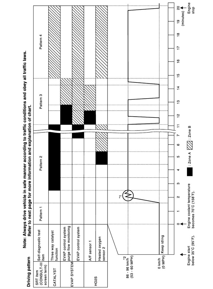
- The time required for each diagnosis varies with road surface conditions, weather, altitude, individual driving habits, etc.Zone A refers to the range where the time, required for the diagnosis under normal conditions*, is the shortest.Zone B refers to the range where the diagnosis can still be performed if the diagnosis is not completed within zone A.
- Sea level
- Flat road
- Ambient air temperature: 20 - 30°C (68 - 86°F)
- Diagnosis is performed as quickly as possible under normal conditions.Under different conditions [For example: ambient air temperature other than 20 - 30°C (68 - 86°F)], diagnosis may also be performed.
- The engine is started at the engine coolant temperature of −10 to 35°C (14 to 95°F)(where the voltage between the ECM terminal 71 and ground is 3.0 - 4.3 V).
- The engine must be operated at idle speed until the engine coolant temperature is greater than 70°C (158°F) (where the voltage between the ECM terminal 71 and ground is lower than 1.4 V).
- The engine is started at the fuel tank temperature of warmer than 0°C (32°F) (where the voltage between the ECM terminal 106 and ground is less than 4.1 V).
- When steady-state driving is performed again even after it is interrupted, each diagnosis can be conducted. In this case, the time required for diagnosis may be extended.
- Operate vehicle following the driving pattern shown in the figure.
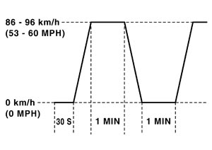
- Release the accelerator pedal during deceleration of vehicle speed from 90 km/h (56 MPH) to 0 km/h (0 MPH).
- The accelerator pedal must be held very steady during steady-state driving.
- If the accelerator pedal is moved, the test must be conducted again.
*2: Checking the vehicle speed with GST is advised.
 Suggested Transmission Gear Position for A/T Models
Set the selector lever in the A position with the overdrive switch turned ON.
Test Value and Test Limit
The following is the information specified in Service $06 of SAE J1979.
The test value is a parameter used to determine whether a system/circuit diagnostic test is OK or NG while being monitored by the ECM during self-diagnosis. The test limit is a reference value which is specified as the maximum or minimum value and is compared with the test value being monitored.
These data (test value and test limit) are specified by On Board Monitor ID(OBDMID), Test ID (TID), Unit and Scaling ID and can be displayed on the GST screen.
The items of the test value and test limit will be displayed with GST screen which items are provided by the ECM. (eg., if bank 2 is not applied on this vehicle, only the items of bank 1 are displayed)
| Item | OBDMID | Self-diagnostic test item | DTC | Test value and Test limit (GST display) | Description | |
| TID | Unit and Scaling ID | |||||
| HO2S | 01H | Air fuel ratio (A/F) sensor 1 (Bank 1) | P0131 | 83H | 0BH | Minimum sensor output voltage for test cycle |
| P0131 | 84H | 0BH | Maximum sensor output voltage for test cycle | |||
| P0130 | 85H | 0BH | Minimum sensor output voltage for test cycle | |||
| P0130 | 86H | 0BH | Maximum sensor output voltage for test cycle | |||
| P0133 | 87H | 04H | Response rate: Response ratio (Lean to Rich) | |||
| P0133 | 88H | 04H | Response rate: Response ratio (Rich to Lean) | |||
| P2A00 | 89H | 84H | The amount of shift in air fuel ratio | |||
| P2A00 | 8AH | 84H | The amount of shift in air fuel ratio | |||
| P0130 | 8BH | 0BH | Difference in sensor output voltage | |||
| P0133 | 8CH | 83H | Response gain at the limited frequency | |||
| 02H | Heated oxygen sensor 2 (Bank 1) | P0138 | 07H | 0CH | Minimum sensor output voltage for test cycle | |
| P0137 | 08H | 0CH | Maximum sensor output voltage for test cycle | |||
| P0138 | 80H | 0CH | Sensor output voltage | |||
| P0139 | 81H | 0CH | Difference in sensor output voltage | |||
| 03H | Heated oxygen sensor 3 (Bank 1) | P0143 | 07H | 0CH | Minimum sensor output voltage for test cycle | |
| P0144 | 08H | 0CH | Maximum sensor output voltage for test cycle | |||
| P0146 | 80H | 0CH | Sensor output voltage | |||
| P0145 | 81H | 0CH | Difference in sensor output voltage | |||
| HO2S | 05H | Air fuel ratio (A/F) sensor 1 (Bank 2) | P0151 | 83H | 0BH | Minimum sensor output voltage for test cycle |
| P0151 | 84H | 0BH | Maximum sensor output voltage for test cycle | |||
| P0150 | 85H | 0BH | Minimum sensor output voltage for test cycle | |||
| P0150 | 86H | 0BH | Maximum sensor output voltage for test cycle | |||
| P0153 | 87H | 04H | Response rate: Response ratio (Lean to Rich) | |||
| P0153 | 88H | 04H | Response rate: Response ratio (Rich to Lean) | |||
| P2A03 | 89H | 84H | The amount of shift in air fuel ratio | |||
| P2A03 | 8AH | 84H | The amount of shift in air fuel ratio | |||
| P0150 | 8BH | 0BH | Difference in sensor output voltage | |||
| P0153 | 8CH | 83H | Response gain at the limited frequency | |||
| 06H | Heated oxygen sensor 2 (Bank 2) | P0158 | 07H | 0CH | Minimum sensor output voltage for test cycle | |
| P0157 | 08H | 0CH | Maximum sensor output voltage for test cycle | |||
| P0158 | 80H | 0CH | Sensor output voltage | |||
| P0159 | 81H | 0CH | Difference in sensor output voltage | |||
| 07H | Heated oxygen sensor 3 (Bank2) | P0163 | 07H | 0CH | Minimum sensor output voltage for test cycle | |
| P0164 | 08H | 0CH | Maximum sensor output voltage for test cycle | |||
| P0166 | 80H | 0CH | Sensor output voltage | |||
| P0165 | 81H | 0CH | Difference in sensor output voltage | |||
| CATALYST | 21H | Three way catalyst function (Bank1) | P0420 | 80H | 01H | O2 storage index |
| P0420 | 82H | 01H | Switching time lag engine exhaust index value | |||
| P2423 | 83H | 0CH | Difference in 3rd O2 sensor output voltage | |||
| P2423 | 84H | 84H | O2 storage index in HC trap catalyst | |||
| 22H | Three way catalyst function (Bank2) | P0430 | 80H | 01H | O2 storage index | |
| P0430 | 82H | 01H | Switching time lag engine exhaust index value | |||
| P2424 | 83H | 0CH | Difference in 3rd O2 sensor output voltage | |||
| P2424 | 84H | 84H | O2 storage index in HC trap catalyst | |||
| EGR SYSTEM | 31H | EGR function | P0400 | 80H | 96H | Low Flow Faults: EGR temp change rate (short term) |
| P0400 | 81H | 96H | Low Flow Faults: EGR temp change rate (long term) | |||
| P0400 | 82H | 96H | Low Flow Faults: Difference between max EGR temp and EGR temp under idling condition | |||
| P0400 | 83H | 96H | Low Flow Faults: Max EGR temp | |||
| P1402 | 84H | 96H | High Flow Faults: EGR temp increase rate | |||
| VVT SYSTEM | 35H | VVT Monitor (Bank1) | P0011 | 80H | 9DH | VTC intake function diagnosis (VTC alignment check diagnosis) |
| P0014 | 81H | 9DH | VTC exhaust function diagnosis (VTC alignment check diagnosis) | |||
| P0011 | 82H | 9DH | VTC intake function diagnosis (VTC drive failure diagnosis) | |||
| P0014 | 83H | 9DH | VTC exhaust function diagnosis (VTC drive failure diagnosis) | |||
| 36H | VVT Monitor (Bank2) | P0021 | 80H | 9DH | VTC intake function diagnosis (VTC alignment check diagnosis) | |
| P0024 | 81H | 9DH | VTC exhaust function diagnosis (VTC alignment check diagnosis) | |||
| P0021 | 82H | 9DH | VTC intake function diagnosis (VTC drive failure diagnosis) | |||
| P0024 | 83H | 9DH | VTC exhaust function diagnosis (VTC drive failure diagnosis) | |||
| EVAP SYSTEM | 39H | EVAP control system leak (Cap Off) | P0455 | 80H | 0CH | Difference in pressure sensor output voltage before and after pull down |
| 3BH | EVAP control system leak (Small leak) | P0442 | 80H | 05H | Leak area index (for more than 0.04 inch) | |
| 3CH | EVAP control system leak (Very small leak) | P0456 | 80H | 05H | Leak area index (for more than 0.02 inch) | |
| P0456 | 81H | FDH | Maximum internal pressure of EVAP system during monitoring | |||
| 3DH | Purge flow system | P0441 | 83H | 0CH | Difference in pressure sensor output voltage before and after vent control valve close | |
| O2 SENSOR HEATER | 41H | A/F sensor 1 heater (Bank 1) | Low Input:P0031 High Input:P0032 | 81H | 0BH | Converted value of Heater electric current to voltage |
| 42H | Heated oxygen sensor 2 heater (Bank 1) | Low Input:P0037 High Input:P0038 | 80H | 0CH | Converted value of Heater electric current to voltage | |
| 43H | Heated oxygen sensor 3 heater (Bank 1) | P0043 | 80H | 0CH | Converted value of Heater electric current to voltage | |
| 45H | A/F sensor 1 heater (Bank 2) | Low Input:P0051 High Input:P0052 | 81H | 0BH | Converted value of Heater electric current to voltage | |
| 46H | Heated oxygen sensor 2 heater (Bank 2) | Low Input:P0057 High Input:P0058 | 80H | 0CH | Converted value of Heater electric current to voltage | |
| 47H | Heated oxygen sensor 3 heater (Bank 2) | P0063 | 80H | 0CH | Converted value of Heater electric current to voltage | |
| SECONDARY AIR | 71H | Secondary Air system | P0411 | 80H | 01H | Secondary Air Injection System Incorrect Flow Detected |
| Bank1: P0491 Bank2: P0492 | 81H | 01H | Secondary Air Injection System Insufficient Flow | |||
| P2445 | 82H | 01H | Secondary Air Injection System Pump Stuck Off | |||
| P2448 | 83H | 01H | Secondary Air Injection System High Airflow | |||
| Bank1: P2440 Bank2: P2442 | 84H | 01H | Secondary Air Injection System Switching Valve Stuck Open | |||
| P2440 | 85H | 01H | Secondary Air Injection System Switching Valve Stuck Open | |||
| P2444 | 86H | 01H | Secondary Air Injection System Pump Stuck On | |||
| FUEL SYSTEM | 81H | Fuel injection system function (Bank 1) | P0171 or P0172 | 80H | 2FH | Long term fuel trim |
| P0171 or P0172 | 81H | 24H | The number of lambda control clamped | |||
| 82H | Fuel injection system function (Bank 2) | P0174 or P0175 | 80H | 2FH | Long term fuel trim | |
| P0174 or P0175 | 81H | 24H | The number of lambda control clamped | |||
| MISFIRE | A1H | Multiple Cylinder Misfires | P0301 | 80H | 24H | Misfiring counter at 1000 revolution of the first cylinder |
| P0302 | 81H | 24H | Misfiring counter at 1000 revolution of the second cylinder | |||
| P0303 | 82H | 24H | Misfiring counter at 1000 revolution of the third cylinder | |||
| P0304 | 83H | 24H | Misfiring counter at 1000 revolution of the fourth cylinder | |||
| P0305 | 84H | 24H | Misfiring counter at 1000 revolution of the fifth cylinder | |||
| P0306 | 85H | 24H | Misfiring counter at 1000 revolution of the sixth cylinder | |||
| P0307 | 86H | 24H | Misfiring counter at 1000 revolution of the seventh cylinder | |||
| P0308 | 87H | 24H | Misfiring counter at 1000 revolution of the eighth cylinder | |||
| P0300 | 88H | 24H | Misfiring counter at 1000 revolution of the multiple cylinders | |||
| P0301 | 89H | 24H | Misfiring counter at 200 revolution of the first cylinder | |||
| P0302 | 8AH | 24H | Misfiring counter at 200 revolution of the second cylinder | |||
| P0303 | 8BH | 24H | Misfiring counter at 200 revolution of the third cylinder | |||
| P0304 | 8CH | 24H | Misfiring counter at 200 revolution of the fourth cylinder | |||
| P0305 | 8DH | 24H | Misfiring counter at 200 revolution of the fifth cylinder | |||
| P0306 | 8EH | 24H | Misfiring counter at 200 revolution of the sixth cylinder | |||
| P0307 | 8FH | 24H | Misfiring counter at 200 revolution of the seventh cylinder | |||
| P0308 | 90H | 24H | Misfiring counter at 200 revolution of the eighth cylinder | |||
| P0300 | 91H | 24H | Misfiring counter at 1000 revolution of the single cylinder | |||
| P0300 | 92H | 24H | Misfiring counter at 200 revolution of the single cylinder | |||
| P0300 | 93H | 24H | Misfiring counter at 200 revolution of the multiple cylinders | |||
| MISFIRE | A2H | No.1 Cylinder Misfire | P0301 | 0BH | 24H | EWMA (Exponential Weighted Moving Average) misfire counts for last 10 driving cycles |
| P0301 | 0CH | 24H | Misfire counts for last/current driving cycles | |||
| A3H | No.2 Cylinder Misfire | P0302 | 0BH | 24H | EWMA (Exponential Weighted Moving Average) misfire counts for last 10 driving cycles | |
| P0302 | 0CH | 24H | Misfire counts for last/current driving cycles | |||
| A4H | No.3 Cylinder Misfire | P0303 | 0BH | 24H | EWMA (Exponential Weighted Moving Average) misfire counts for last 10 driving cycles | |
| P0303 | 0CH | 24H | Misfire counts for last/current driving cycles | |||
| A5H | No.4 Cylinder Misfire | P0304 | 0BH | 24H | EWMA (Exponential Weighted Moving Average) misfire counts for last 10 driving cycles | |
| P0304 | 0CH | 24H | Misfire counts for last/current driving cycles | |||
| A6H | No.5 Cylinder Misfire | P0305 | 0BH | 24H | EWMA (Exponential Weighted Moving Average) misfire counts for last 10 driving cycles | |
| P0305 | 0CH | 24H | Misfire counts for last/current driving cycles | |||
| A7H | No.6 Cylinder Misfire | P0306 | 0BH | 24H | EWMA (Exponential Weighted Moving Average) misfire counts for last 10 driving cycles | |
| P0306 | 0CH | 24H | Misfire counts for last/current driving cycles | |||
| A8H | No.7 Cylinder Misfire | P0307 | 0BH | 24H | EWMA (Exponential Weighted Moving Average) misfire counts for last 10 driving cycles | |
| P0307 | 0CH | 24H | Misfire counts for last/current driving cycles | |||
| A9H | No.8 Cylinder Misfire | P0308 | 0BH | 24H | EWMA (Exponential Weighted Moving Average) misfire counts for last 10 driving cycles | |
| P0308 | 0CH | 24H | Misfire counts for last/current driving cycles | |||