FRONT COIL SPRING AND SHOCK ABSORBER
Exploded View
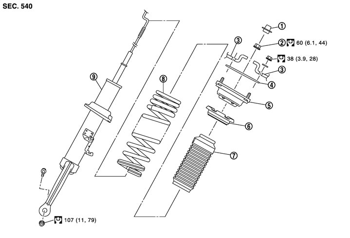
|
1. |
Cap |
2. |
Piston rod lock nut |
3. |
Vehicle body |
|
4. |
Mounting seal |
5. |
Mount insulator |
6. |
Rubber seat |
|
7. |
Bound bumper |
8. |
Coil spring |
9. |
Shock absorber |
|
Refer to Components for the symbols in the figure. |
|||||
Removal and Installation
 REMOVAL
- 1.Remove tires with power tool.
- 2.Remove steering knuckle. Refer to Exploded View.
- 3.Remove stabilizer connecting rod. Refer to Exploded View.
- 4.Separate shock absorber from transverse link with power tool.
- 5.Separate shock absorber actuator harness connector (1).
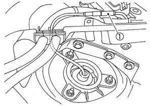
- 6.Remove shock absorber assembly.
NOTE:
If removing shock absorber is difficult, loosen upper link mounting bolts (vehicle side). INSTALLATIONNote the following, and install in the reverse order of removal.
- Never pull the shock absorber harness connector.
- Perform final tightening of bolts and nuts at the vehicle installation position (rubber bushing), under unladen conditions with tires on level ground.
Disassembly and Assembly
DISASSEMBLY■ CAUTION ■
- Never damage shock absorber piston rod when removing components from shock absorber.
- Before disassembly, distinguish coil spring right and left.
- 1.Install shock absorber attachment (A) [SST: ST35652000 ( — )] to shock absorber and it in a vise.
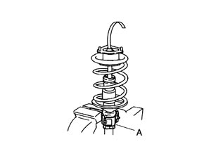
■ CAUTION ■
When installing the shock absorber attachment to shock absorber, wrap a waste cloth around shock absorber to protect it from damage.- 2.Using a spring compressor (A) (commercial service tool), compress coil spring between rubber seat and shock absorber until coil spring with a spring compressor is free.
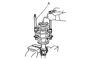
■ CAUTION ■
Always a spring compressor is installed coil spring. Compress coil spring.- 3.Remove cap.
- 4.Check coil spring with a spring compressor between rubber seat and shock absorber is free. And then remove piston rod lock nut while securing the piston rod tip so that piston rod does not turn with sensor socket (A) [17 mm (0.67 in)].
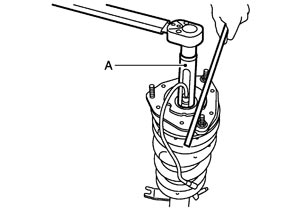
■ CAUTION ■
Never damage shock absorber actuator harness connector.- 5.Remove mounting seal, mount insulator, rubber seat, bound bumper from shock absorber.
- 6.After removing coil spring with a spring compressor, then gradually release a spring compressor.
■ CAUTION ■
Loosen while checking coil spring attachment position does not move.- 7.Remove the shock absorber attachment from shock absorber.
ASSEMBLY- 1.Install shock absorber attachment (A) [SST: ST35652000 ( — )] to shock absorber and secure it in a vise.
■ CAUTION ■
When installing the shock absorber attachment to shock absorber, wrap a waste cloth around shock absorber to protect it from damage.- 2.Compress the coil spring using a spring compressor, and then set it to the shock absorber.
- Install the coil spring with larger-diameter side (A) facing up and the smaller-diameter side (B) facing down. Then, check that the paint mark (C) is facing downward.
- Start compressing the coil spring after checking that the spring compressor is completely installed to the coil spring.
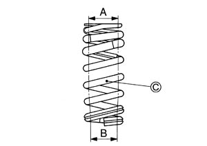
■ CAUTION ■
- 3.Assemble the rubber seat to the mount insulator as shown in the figure.
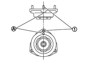
■ CAUTION ■
Align the positions of the paint make (A) and the stud bolt (1). - 4.Apply soapy water to bound bumper.
■ CAUTION ■
Never use machine oil.- 5.Install the rubber seat and mount insulator to the shock absorber.
- Install the mount insulator so that the stud bolt is in the position shown in the figure.
Angle (E) : 18° - Install the coil spring so that the lower edge is in the position (F) of the lower seat shown in the figure. ■ CAUTION ■Never lift up the shock absorber with the shock absorber harness connector.
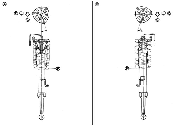
| A. Right side | B. Left side | C. Vehicle front |
| D. Vehicle out side |
- 6.Secure piston rod tip so that piston rod does not turn, then tighten piston rod lock nut to the specified torque with sensor socket [17 mm (0.67 in)].
■ CAUTION ■
Never damage shock absorber actuator harness connector.- 7.Gradually release a spring compressor, and remove coil spring.
■ CAUTION ■
Loosen while checking coil spring attachment position does not move.- 8.Remove the shock absorber attachment from shock absorber.
- 9.Install the mounting seal to mount insulator.
Inspection
INSPECTION AFTER INSTALLATION- 1.Check shock absorber actuator harness connector (1) for proper connection.
- 2.Check wheel sensor harness connector for proper connection. Refer to Exploded View (GT-R certified NISSAN dealer).
- 3.Check wheel alignment. Refer to Adjustment.
- 4.Adjust neutral position of steering angle sensor. Refer to Special Repair Requirement (GT-R certified NISSAN dealer).
INSPECTION AFTER DISASSEMBLY Shock Absorber
Check the following items, and replace the part if necessary.
- Shock absorber for deformation, cracks or damage.
- Piston rod for damage, uneven wear or distortion.
- Oil leakage.
- Shock absorber harness connector for damage.
Mount Insulator and Rubber Parts InspectionCheck mount insulator for cracks and rubber parts for wear. Replace it if necessary
Coil SpringCheck coil spring for cracks, wear or damage. Replace it if necessary.