FUEL GAUGE
METER SYSTEM
System Diagram

System Description
 CONTROL OUTLINE
The combination meter reads the fuel gauge signal (resistance value) from the fuel gauge unit, and indicates the fuel level to the fuel gauge.
REFUEL CONTROLWhen the ignition switch is turned from ON to OFF, or when all the following conditions are met, it performs a control to move the fuel gauge pointer faster than normal.
- Ignition switch ON
- Vehicle stop status
- Fuel level fluctuation is 15
 (4 US gal, 3-3/10 lmp gal) or more.
Component Parts Location
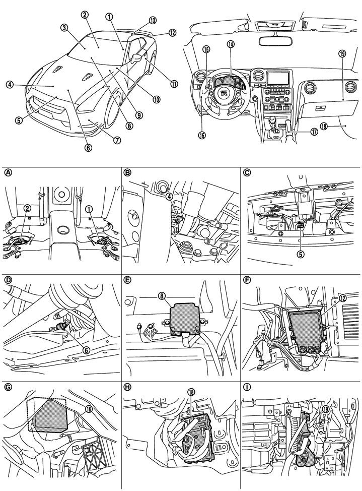
|
1. |
Fuel level sensor unit (Sub) |
2. |
Fuel level sensor unit (Main) |
3. |
Door switch (passenger side) |
|
4. |
Oil pressure sensor |
5. |
Ambient sensor |
6. |
Oil level sensor |
|
7. |
Washer level switch |
8. |
AWD control unit |
9. |
Brake fluid level switch |
|
10. |
ABS actuator and electric unit (control unit) |
11. |
Door switch (driver side) |
12. |
TCM |
|
13. |
Trunk switch |
14. |
Combination meter |
15. |
Combination switch (Lighting switch) |
|
16. |
Low tire pressure warning control unit |
17. |
Parking brake |
18. |
BCM |
|
19. |
ECM |
|
|
|
|
|
A. |
Under rear seat |
B. |
Right side of engine |
C. |
Radiator core support (center) |
|
D. |
Oil pan LH upper |
E. |
Front RH seat under |
F. |
Trunk room left back |
|
G. |
Lower instrument panel LH |
H. |
Dashboard side lower (passenger seat side) |
I. |
Glove box assembly back |
Component Description
|
Unit |
Description |
|
Combination meter |
Reads the fuel gauge signal (resistance value) from the fuel gauge unit, and indicates the remaining fuel level. |
|
Fuel level sensor unit |
Detects the fuel level in fuel tank using the fuel gauge unit, and transmits the fuel gauge signal to the combination meter. |