METER ILLUMINATION CONTROL
METER SYSTEM
System Diagram
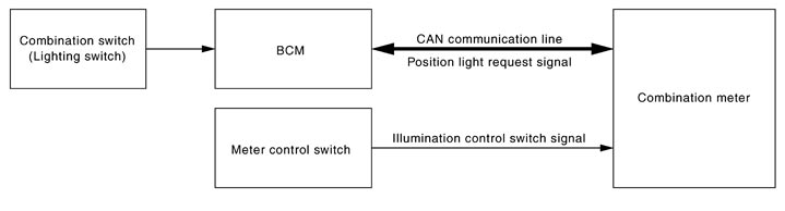
System Description
 METER ILLUMINATION CONTROL FUNCTION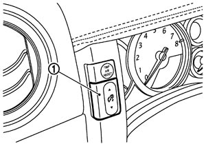
Component Parts Location
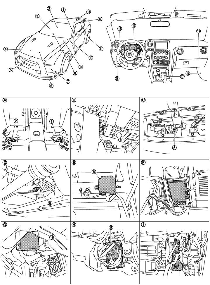
|
1. |
Fuel level sensor unit (Sub) |
2. |
Fuel level sensor unit (Main) |
3. |
Door switch (passenger side) |
|
4. |
Oil pressure sensor |
5. |
Ambient sensor |
6. |
Oil level sensor |
|
7. |
Washer level switch |
8. |
AWD control unit |
9. |
Brake fluid level switch |
|
10. |
ABS actuator and electric unit (control unit) |
11. |
Door switch (driver side) |
12. |
TCM |
|
13. |
Trunk switch |
14. |
Combination meter |
15. |
Combination switch (Lighting switch) |
|
16. |
Low tire pressure warning control unit |
17. |
Parking brake |
18. |
BCM |
|
19. |
ECM |
|
|
|
|
|
A. |
Under rear seat |
B. |
Right side of engine |
C. |
Radiator core support (center) |
|
D. |
Oil pan LH upper |
E. |
Front RH seat under |
F. |
Trunk room left back |
|
G. |
Lower instrument panel LH |
H. |
Dashboard side lower (passenger seat side) |
I. |
Glove box assembly back |
Component Description
|
Unit |
Description |
|
|
Combination meter |
Controls the meter illumination with the illumination control switch signal from the meter control switch and the position light request signal from BCM via CAN communication. |
|
|
BCM |
Transmits the position light request signal to the combination meter via CAN communication. |
|
|
Meter control switch |
Transmits the following signals to the combination meter. |
|
|
|
|
|
Combination switch (Lighting switch) |
Using the combination switch reading function, BCM reads the combination switch status. |
|