UP-SHIFT INDICATOR
METER SYSTEM
System Diagram
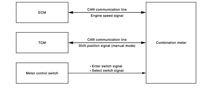
System Description
- The combination meter receives the engine speed signal from ECM and the shift position signal (manual mode range) from TCM via CAN communication, and illuminates/turns off/blinks the up-shift indicator.
- The engine speed at which the up-shift indicator is illuminated/turned off/blinked can be set with the setting function of vehicle information display.
- OFF: All of the up-shift indicators do not illuminate.
- 3,000 to 6,300 rpm: Engine speed can be set at which the up-shift indicator (green) is illuminated.
- AUTO: Up-shift indicator (green) does not illuminate. The up-shift indicator (yellow) and up-shift indicator (red) is turned on/off according to the set value.
 UP-SHIFT INDICATOR (GREEN)
- Using the setting function of vehicle information display, the up-shift warning speed can be set.
- The up-shift indicator (green) is illuminated/turned off/blinked according to the engine speed.
- OFF: If the actual engine speed is lower than the arbitrarily set engine speed, which is 3,000 to 6,300 rpm set by the setting function of vehicle information display, by 500 rpm or more, the up-shift warning lamp is turned OFF. Also, while the up-shift indicator (green) is blinking or illuminated, if the actual engine speed becomes lower than the arbitrarily set engine speed by 600 rpm or more, the up-shift warning lamp is turned OFF.
- Blink: If the actual engine speed is lower than the arbitrarily set engine speed by 500 rpm or more, the up-shift indicator (green) is blinked.
- ON: When the actual engine speed exceeds the arbitrarily set engine speed, the up-shift indicator (green) is illuminated.Also, while the up-shift indicator (green) is blinking or illuminated, if the actual engine speed becomes lower than the arbitrarily set engine speed by 100 rpm or more, the up-shift indicator is blinked.
UP-SHIFT INDICATOR (YELLOW)The up-shift indicator (yellow) is turned ON/OFF according to the engine speed.
- OFF: When the engine speed is less than 6,300 rpm, the up-shift indicator (yellow) does not illuminate.Also, while the up-shift indicator (yellow) is illuminated, when the engine speed becomes 6,200 rpm or lower, the up-shift indicator (yellow) is turned OFF.
- ON: When the engine speed becomes 6,300 rpm or more, the up-shift indicator (yellow) is illuminated.
UP-SHIFT INDICATOR (RED)The up-shift indicator (red) is turned ON/OFF according to the engine speed.
- OFF: When the engine speed is less than 6,800 rpm, the up-shift indicator (red) does not illuminate.Also, while the up-shift indicator (red) is illuminated, when the engine speed becomes 6,700 rpm or lower, the up-shift indicator (red) is turned OFF.
- ON: When the engine speed becomes 6,800 rpm or more, the up-shift indicator (red) is illuminated.
Component Parts Location
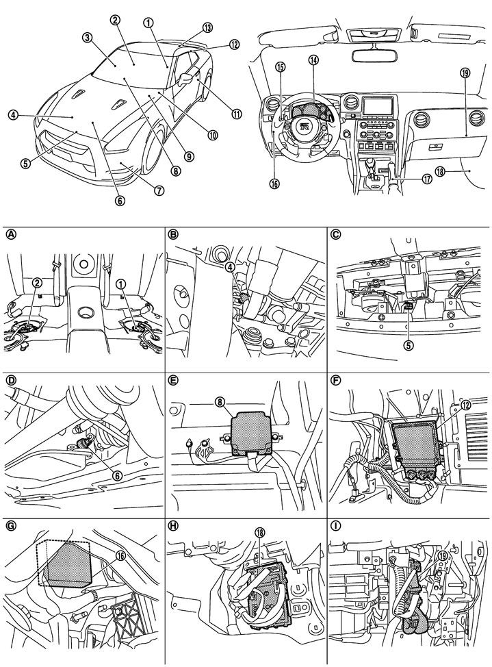
|
1. |
Fuel level sensor unit (Sub) |
2. |
Fuel level sensor unit (Main) |
3. |
Door switch (passenger side) |
|
4. |
Oil pressure sensor |
5. |
Ambient sensor |
6. |
Oil level sensor |
|
7. |
Washer level switch |
8. |
AWD control unit |
9. |
Brake fluid level switch |
|
10. |
ABS actuator and electric unit (control unit) |
11. |
Door switch (driver side) |
12. |
TCM |
|
13. |
Trunk switch |
14. |
Combination meter |
15. |
Combination switch (Lighting switch) |
|
16. |
Low tire pressure warning control unit |
17. |
Parking brake |
18. |
BCM |
|
19. |
ECM |
|
|
|
|
|
A. |
Under rear seat |
B. |
Right side of engine |
C. |
Radiator core support (center) |
|
D. |
Oil pan LH upper |
E. |
Front RH seat under |
F. |
Trunk room left back |
|
G. |
Lower instrument panel LH |
H. |
Dashboard side lower (passenger seat side) |
I. |
Glove box assembly back |
Component Description
|
Unit |
Description |
|
|
Combination meter |
Using the signals received from each unit and switch, controls the shift position indicator. |
|
|
ECM |
Transmits the engine speed signal to the combination meter via CAN communication. |
|
|
TCM |
Transmits the shift position signal (M range) to the combination meter via CAN communication. |
|
|
Meter control switch |
Transmits the following signals to the combination meter. |
|
|
|
|