COMBINATION METER
Reference Value
 CONSULT‐III DATA MONITOR REFERENCE VALUES
|
Monitor item |
Measuring condition |
Standard/Status | |
| SPEED METER [km/h] | Ignition switch ON | While driving | Equivalent to speedometer reading NOTE: 655.35 is displayed when the malfunction signal is received |
| SPEED OUTPUT [km/h] | Ignition switch ON | While driving | Equivalent to speedometer reading NOTE: 655.35 is displayed when the malfunction signal is received |
| ODO OUTPUT [km] | Ignition switch ON | — | Equivalent to odometer reading in combination meter |
| TACHO METER [rpm] | Ignition switch ON | While driving | Approximately the same as tachometer reading NOTE: 8191.875 is displayed when the malfunction signal is received |
| FUEL METER [L] | Ignition switch ON | — | Values according to fuel level |
| W TEMP METER [°C] | Ignition switch ON | — | Values according to engine coolant temperature NOTE: 215 is displayed when the malfunction signal is input |
| ABS W/L | Ignition switch ON | ABS warning lamp ON | On |
| ABS warning lamp OFF | Off | ||
| VDC/TCS IND | Ignition switch ON | VDC OFF indicator lamp ON | On |
| VDC OFF indicator lamp OFF | Off | ||
| SLIP IND | Ignition switch ON | SLIP Indicator lamp ON | On |
| SLIP indicator lamp OFF | Off | ||
| BRAKE W/L | Ignition switch ON | Brake warning lamp ON | On |
| Brake warning lamp OFF | Off | ||
| DOOR W/L | Ignition switch ON |
| On |
| Off | ||
| HI-BEAM IND | Ignition switch ON | High beam indicator lamp ON | On |
| High beam indicator lamp OFF | Off | ||
| TURN IND | Ignition switch ON | Turn signal indicator lamp ON | On |
| Turn signal indicator lamp OFF | Off | ||
| RR FOG IND | Ignition switch ON | This item is displayed, but cannot be monitored. | Off |
| OIL W/L | Ignition switch ON | Oil pressure warning lamp ON | On |
| Oil pressure warning lamp OFF | Off | ||
| LIGHT IND | Ignition switch ON | Tail lamp indicator lamp ON | On |
| Tail lamp indicator lamp OFF | Off | ||
| MIL | Ignition switch ON | MIL ON | On |
| MIL OFF | Off | ||
| CRUISE IND | Ignition switch ON | Cruise indicator lamp ON | On |
| Cruise indicator lamp OFF | Off | ||
| SET IND | Ignition switch ON | SET indicator lamp ON | On |
| SET indicator lamp OFF | Off | ||
| ATC/T‐AMT W/L | Ignition switch ON | Transmission warning lamp ON | On |
| Transmission warning lamp OFF | Off | ||
| 4WD W/L | Ignition switch ON | AWD warning lamp ON | On |
| AWD warning lamp OFF | Off | ||
| FUEL W/L | Ignition switch ON | Low fuel warning display | On |
| Low fuel warning is not displayed | Off | ||
| WASHER W/L | Ignition switch ON | Low washer fluid warning display | On |
| Low washer fluid warning is not displayed | Off | ||
| AIR PRES W/L | Ignition switch ON | Tire pressure warning lamp ON | On |
| Tire pressure warning lamp OFF | Off | ||
| KEY G/Y W/L | Ignition switch ON | KEY warning lamp (green/yellow) ON | On |
| KEY warning lamp (green/yellow) OFF | Off | ||
| LCD | Ignition switch ON | Engine start indication is displayed | B&P I |
| Ignition switch ACC | Engine start indication is displayed | B&P N | |
| Ignition switch LOCK | Key ID NG warning is displayed | ID NG | |
| Ignition switch LOCK | Steering lock rotation operation signal illuminated | ROTAT | |
| Ignition switch LOCK | P engagement warning is displayed | SFT P | |
| Ignition switch LOCK | Key insertion indication is displayed | INSRT | |
| Ignition switch LOCK | Intelligent Key low battery notice warning is displayed | BATT | |
| Ignition switch ON | Key removal warning is displayed | NO KY | |
| Ignition switch LOCK | Key reminder warning is displayed | OUT KY | |
| Ignition switch ON | ACC warning is displayed | LK WN | |
| SHIFT IND | Ignition switch ON | Shift position P is displayed | P |
| Shift position R is displayed | R | ||
| Shift position N is displayed | N | ||
| Shift position A1 is displayed | A1 | ||
| Shift position A2 is displayed | A2 | ||
| Shift position A3 is displayed | A3 | ||
| Shift position A4 is displayed | A4 | ||
| Shift position A5 is displayed | A5 | ||
| Shift position A6 is displayed | A6 | ||
| Shift position M1 is displayed | M1 | ||
| Shift position M2 is displayed | M2 | ||
| Shift position M3 is displayed | M3 | ||
| Shift position M4 is displayed | M4 | ||
| Shift position M5 is displayed | M5 | ||
| Shift position M6 is displayed | M6 | ||
| PKB SW | Ignition switch ON | Parking brake switch ON | On |
| Parking brake switch OFF | Off | ||
| BUCKLE SW | Ignition switch ON | Seat belt not fastened | On |
| Seat belt fastened | Off | ||
| BRAKE OIL SW | Ignition switch ON | Brake fluid level switch ON | On |
| Brake fluid level switch OFF | Off | ||
| A/C AMP CONN | Ignition switch ON | A/C auto amp. is not connected | On |
| A/C auto amp. is connected | Off | ||
| ENTER SW | Ignition switch ON | Enter switch is being pressed | On |
| Enter switch is not pressed | Off | ||
| SELECT SW | Ignition switch ON | Select switch is being pressed | On |
| Select switch is not pressed | Off | ||
| DISTANCE [km] | Ignition switch ON | — | Possible driving distance calculated by combination meter |
| OUTSIDE TEMP [°C] | Ignition switch ON | — | Equivalent to ambient temperature NOTE: This may not match the indicated value on vehicle information display. |
| FUEL LOW SIG | Ignition switch ON | Low fuel warning is displayed | On |
| Low fuel warning is not displayed | Off | ||
| CRANKING SIG | At engine cranking | On | |
| Ignition switch ON | Off | ||
| ST CNT SIG | At engine cranking | On | |
| Ignition switch ON | Off | ||
| BUZZER | Ignition switch ON | Buzzer ON | On |
| Buzzer OFF | Off | ||
| ENG OIL TMP | Ignition switch ON | — | Values according to engine oil temperature |
| ENG OIL PRESS | Ignition switch ON | — | Values according to engine oil pressure |
| TM OIL TMP | Ignition switch ON | — | Values according to transmission oil temperature |
| TM OIL PRESS | Ignition switch ON | — | Values according to transmission oil pressure |
| A/F RATIO | Ignition switch ON | — | Values according to engine air-fuel ratio |
| BOOST PRESS | Ignition switch ON | — | Values according to boost pressure |
| THRTL POSI | Ignition switch ON | — | Values according to throttle position |
| TRQ DSTRBT | Ignition switch ON | — | Values according to front torque distribution rate |
| AMT P SFT | Ignition switch ON | Shift “ P ” warning display ON | On |
| Shift “ P ” warning display OFF | Off | ||
| AMT SYS CHCK | Ignition switch ON | Transmission system check display ON | On |
| Transmission system check display ON | Off | ||
| AMT SFT POSI | Ignition switch ON | Shift lever position warning display ON | On |
| Shift lever position warning display OFF | Off | ||
| AMT OIL TMP H | Ignition switch ON | Transmission oil high temperature warning display ON | On |
| Transmission oil high temperature warning display OFF | Off | ||
| AMT CL TMP H | Ignition switch ON | Transmission clutch high temperature warning display ON | On |
| Transmission clutch high temperature warning display OFF | Off | ||
| AMT CHCK | Ignition switch ON | It is displayed, but not used. | Off |
| AMT MALF | Ignition switch ON | Transmission system warning display ON | On |
| Transmission system warning display OFF | Off | ||
| TPMS FLT TIRE | Ignition switch ON | Run-flat tire warning display ON | On |
| Run-flat tire warning display OFF | Off | ||
| TPMS PRESS L | Ignition switch ON | Low tire pressure warning display ON | On |
| Low tire pressure warning display OFF | Off | ||
| TPMS MALF | Ignition switch ON | Tire pressure monitoring system warning display ON | On |
| Tire pressure monitoring system warning display OFF | Off | ||
| 4WD CL TMP H | Ignition switch ON | AWD clutch high temperature warning display ON | On |
| AWD clutch high temperature warning display OFF | Off | ||
| 4WD TIRE CHCK | Ignition switch ON | Front/rear tire size discrepancy warning display ON | On |
| Front/rear tire size discrepancy warning display OFF | Off | ||
| 4WD SYS MALF | Ignition switch ON | AWD system warning display ON | On |
| AWD system warning display OFF | Off | ||
| ABS MALF | Ignition switch ON | Anti-lock braking system (ABS) warning display ON | On |
| Anti-lock braking system (ABS) warning display OFF | Off | ||
| VDC MALF | Ignition switch ON | Vehicle dynamic control (VDC) system warning display ON | On |
| Vehicle dynamic control (VDC) system warning display OFF | Off | ||
| ENG SYS CHCK | Ignition switch ON | Engine system warning display ON | On |
| Engine system warning display OFF | Off | ||
| ASCD SYS MALF | Ignition switch ON | CRUISE control system warning display ON | On |
| CRUISE control system warning display OFF | Off | ||
| ASCD REQ SPD | Ignition switch ON | ASCD set vehicle speed | On |
| ASCD set vehicle speed | Off | ||
| ASCD STATUS | Ignition switch ON | ASCD system OFF | Off |
| ASCD system ON | ASCD | ||
| ASCD SPD BLNK | Ignition switch ON | While driving | Same value as ASCD set vehicle speed |
TERMINAL LAYOUT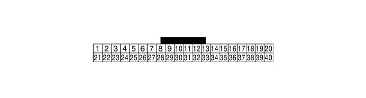 INPUT/OUTPUT SIGNAL STANDARD
|
Terminal No. (Wire color) |
Description |
Condition |
Value (Approx.) |
|||
|
+ |
– |
Signal name |
Input/ Output |
|||
|
1 (V) |
Ground |
Battery power supply |
Input |
Ignition switch OFF |
— |
Battery voltage |
|
2 (W) |
Ground |
Ignition power supply |
Input |
Ignition switch ON |
— |
Battery voltage |
|
3 (B) |
Ground |
Ground |
— |
Ignition switch ON |
— |
Approx. 0 V |
|
5 (B) |
Ground |
Ground |
— |
Ignition switch ON |
— |
Approx. 0 V |
|
6 (W) |
Ground |
Meter control switch ground |
— |
Ignition switch ON |
— |
Approx. 0 V |
|
7 (Y) |
Ground |
A/C auto amp. connection recognition signal |
Input |
Ignition switch ON |
— |
Approx. 5 V |
|
8 (SB) |
Ground |
Ambient sensor ground |
— |
Ignition switch ON |
— |
Approx. 0 V |
|
9 (P) |
Ground |
Ambient sensor |
Input |
Ignition switch ON |
— |
Refer to Component Inspection. |
|
12 (L) |
Ground |
Vehicle speed signal (2-pulse) |
Output |
Ignition switch ON |
Vehicle speed is approximately 40 km/h (25 MPH) |
NOTE:
The maximum voltage varies depending on the specification (destination unit).
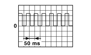
|
|
13 (V) |
Ground |
Vehicle speed signal (8-pulse) |
Output |
Ignition switch ON |
Vehicle speed is approximately 40 km/h (25MPH) |
NOTE:
The maximum voltage varies depending on the specification (destination unit).
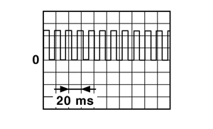
|
|
14 (B) |
Ground |
Oil pressure sensor ground |
— |
Ignition switch ON |
— |
Approx. 0 V |
|
15 (R) |
Ground |
Air bag signal |
Input |
Ignition switch ON |
Air bag warning lamp ON |
Approx. 5 V |
|
Air bag warning lamp OFF |
Approx. 0V |
|||||
|
18 (L) |
Ground |
Fuel gauge signal ground |
— |
Ignition switch ON |
— |
Approx. 0 V |
|
19 (R) |
Ground |
Oil level sensor ground |
— |
Ignition switch ON |
— |
Approx. 0 V |
|
20 (W) |
Ground |
Oil level sensor signal |
— |
Ignition switch ON |
— |
Refer to Component Inspection. |
|
21 (L) |
Ground |
CAN-H |
— |
Ignition switch ON |
— |
— |
|
22 (P) |
Ground |
CAN-L |
— |
Ignition switch ON |
— |
— |
|
23 (LG) |
6 (W) |
Illumination control switch signal (–) |
Input |
Ignition switch ON |
When   switch is pressed switch is pressed |
Approx. 0 V |
|
Other than the above |
Approx. 5 V |
|||||
|
24 (BR) |
6 (W) |
Illumination control switch signal (+) |
Input |
Ignition switch ON |
When  switch is pressed switch is pressed |
Approx. 0 V |
|
Other than the above |
Approx. 5 V |
|||||
|
25 (L) |
6 (W) |
Trip A/B reset switch signal |
Input |
Ignition switch ON |
When trip A/B reset switch is pressed |
Approx. 0 V |
|
Other than the above |
Approx. 5 V |
|||||
|
26 (O) |
6 (W) |
Enter switch signal |
Input |
Ignition switch ON |
When  switch is pressed switch is pressed |
Approx. 0 V |
|
Other than the above |
Approx. 5 V |
|||||
|
27 (SB) |
6 (W) |
Select switch signal |
Input |
Ignition switch ON |
When  switch is pressed switch is pressed |
Approx. 0 V |
|
Other than the above |
Approx. 5 V |
|||||
|
28 (BR) |
Ground |
Alternator signal |
Input |
Ignition switch ON |
Charging warning lamp ON |
Approx. 0 V |
|
Charging warning lamp OFF |
Approx. 12 V |
|||||
|
29 (G) |
Ground |
Seat belt buckle switch signal (passenger side) |
Input |
Ignition switch ON |
|
Approx. 12 V |
|
Approx. 0 V |
|||||
|
30 (SB) |
Ground |
Seat belt buckle switch signal (driver side) |
Input |
Ignition switch ON |
When driver seat belt is fastened |
Approx. 12 V |
|
When driver seat belt is unfastened |
Approx. 0 V |
|||||
|
31 (V) |
Ground |
Parking brake switch signal |
Input |
Ignition switch ON |
Parking brake applied |
Approx. 0 V |
|
Parking brake released |
Approx. 5 V |
|||||
|
32 (V) |
Ground |
Brake fluid level switch signal |
Input |
Ignition switch ON |
Brake fluid level is normal |
Approx. 0 V |
|
Brake fluid level is MIN level or less |
Approx. 5 V |
|||||
|
33 (L) |
Ground |
Washer level switch signal |
Input |
Ignition switch ON |
Low washer fluid warning display ON |
Approx. 0 V |
|
Low washer fluid warning display OFF |
Approx. 5 V |
|||||
|
34 (GR) |
Ground |
Oil pressure sensor power |
Output |
Ignition switch ON |
— |
Approx. 5 V |
|
35 (W) |
Ground |
Oil pressure sensor signal |
Input |
Ignition switch ON |
— |
Refer to Component Inspection. |
|
38 (W) |
Ground |
Fuel gauge signal |
Input |
Ignition switch ON |
— |
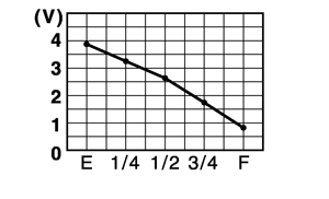
|
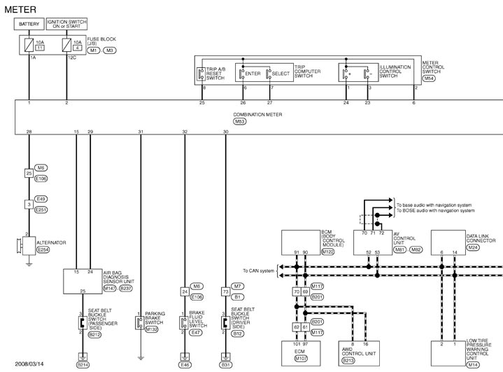
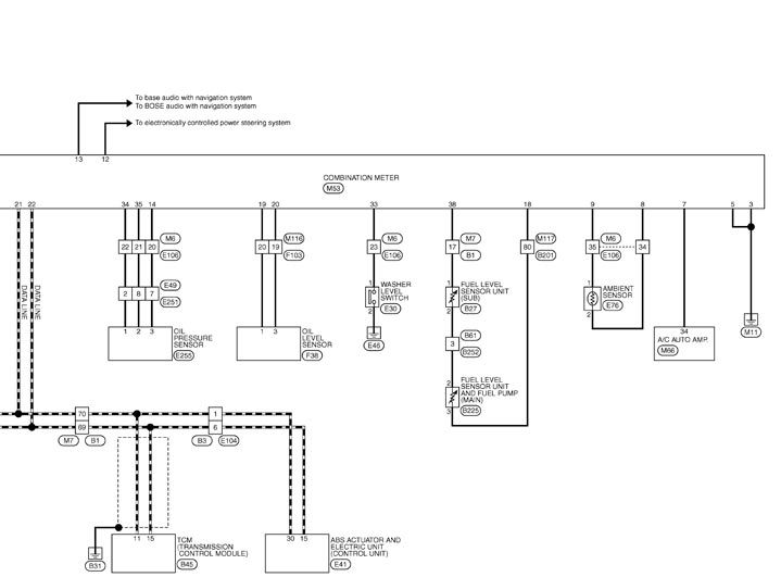
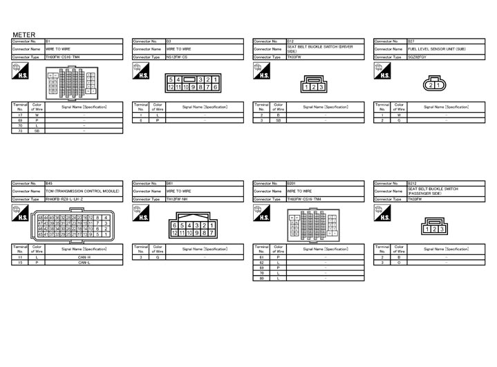
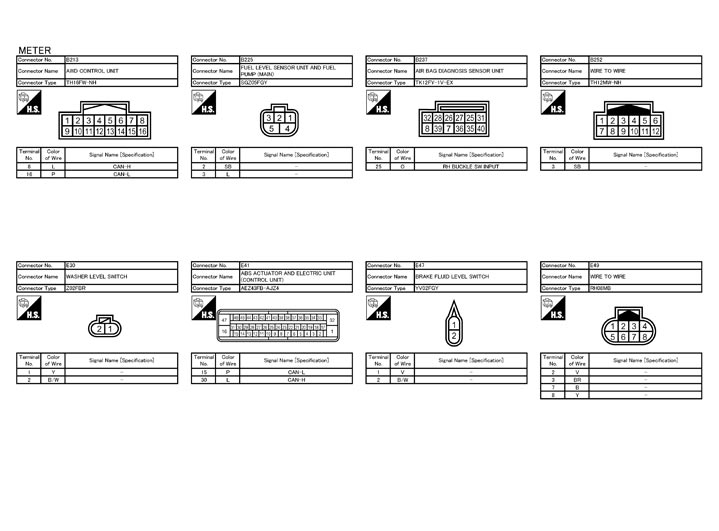
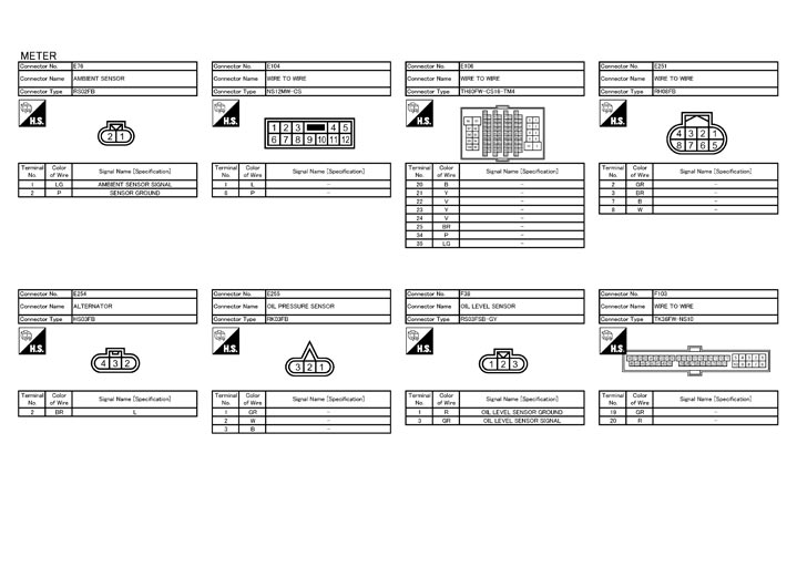
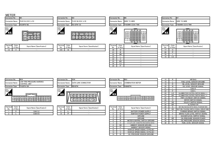
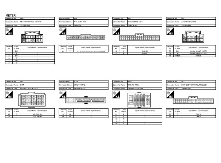
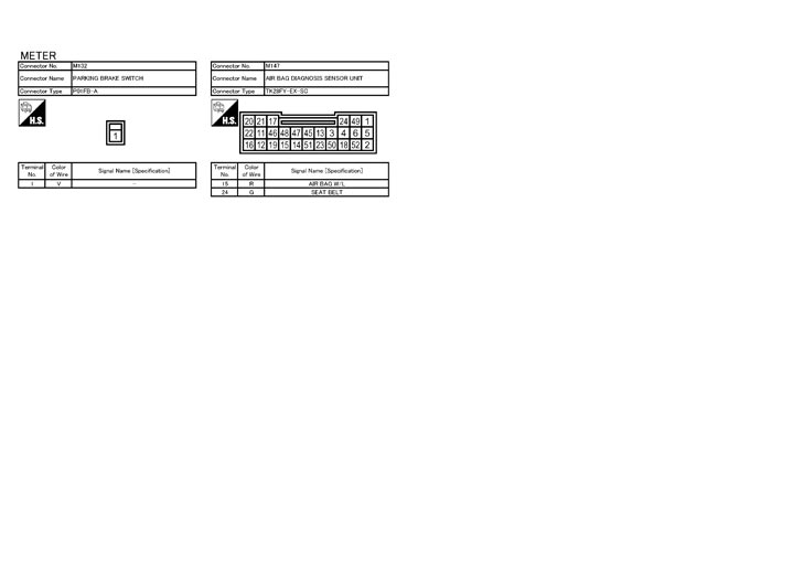
Wiring Diagram - METER -
Fail-safe
FAIL-SAFEIf the CAN communication with each unit is activates, the combination meter broken the fail-safe control.
| System | Processing | |
| Speedometer | Returns to zero when communication is blocked. | |
| Tachometer | ||
| Engine coolant temperature gauge | ||
| Meter illumination control | Shifts to night mode when communication is blocked. | |
| Shift position indicator | Turned OFF when communication is blocked. | |
| Vehicle information display | Door open warning | Indication is turned OFF when communication is blocked. |
| Trunk open warning | ||
| Parking brake release warning | ||
| Shift “ P ” warning | ||
| Transmission system check | ||
| Shift lever position warning | ||
| Transmission clutch high temperature warning | ||
| Transmission oil high temperature warning | ||
| Transmission system warning | ||
| Run-flat tire warning | ||
| Low tire pressure warning | ||
| Tire pressure monitoring system warning | ||
| AWD clutch high temperature warning | ||
| Front/rear tire size discrepancy warning | ||
| AWD system warning | ||
| Anti-lock braking system (ABS) warning | ||
| Vehicle dynamic control (VDC) system warning | ||
| Engine system warning | ||
| CRUISE control system warning | ||
| CRUISE control system status | ||
| Vehicle speed display | 0 km/h (0 MPH) is indicated when communication is blocked. | |
| Possible driving distance | Displays the last calculation result calculated under a normal status when communication is blocked. | |
| Average fuel consumption | ||
| Instantaneous fuel consumption | ||
| Average vehicle speed | ||
| Warning buzzer | Warning is turned OFF when communication is blocked. | |
| Warning lamp/indicator lamp | ABS warning lamp | Turned ON when communication is broken. |
| VDC OFF warning lamp | ||
| SLIP indicator lamp | ||
| Brake warning lamp | ||
| AWD warning lamp | ||
| Tire pressure warning lamp | Blinks first, then illuminates after approximately 1 minute. | |
| High beam indicator lamp | Turned OFF when communication is broken. | |
| Turn signal indicator lamp | ||
| Tail lamp indicator lamp | ||
| MIL | ||
| CRUISE indicator lamp | ||
| SET indicator lamp | ||
| KEY warning lamp | ||
| Up-shift indicator (green) | ||
| Up-shift indicator (yellow) | ||
| Up-shift indicator (red) | ||
| Transmission check warning lamp | ||
DTC Index
NOTE:
Details of time display- CRNT: Displays during the current malfunctioning detection.
- PAST: Displays if any previous malfunction is present when the current status is normal.
- The IGN counter is displayed in the freeze frame data (FFD).
- The IGN counter indicates the number of times ignition switch is turned ON after the DTC detection.
- When a trouble is currently being detected, it displays “0”.
- After the status returns to normal, the indication value is incriminated as “1 → 2 → 3 → ... 38 → 39" every time the ignition switch is turned OFF → ON.
- When the operation count of ignition switch OFF → ON exceeds 39, the indication will be fixed at "39" until the self-diagnosis is deleted.
|
Display contents of CONSULT‐III |
Diagnostic item is detected if ... |
Refer to |
|
CAN COMM CIRCUIT [U1000] |
Combination meter cannot communicate CAN communication signal for 2 seconds or more |
Diagnosis Procedure
|
|
CONTROL UNIT (CAN) [U1010] |
Malfunction is detected during initial diagnosis of combination meter CAN controller |
Diagnosis Procedure
|
|
VEHICLE SPEED [B2205] |
Abnormal vehicle speed signal is received from ABS actuator and electric unit (control unit) for 2 seconds or more |
Diagnosis Procedure
|
|
ENGINE SPEED [B2267] |
ECM continuously transmits abnormal engine speed signal for 2 seconds or more |
Diagnosis Procedure
|
|
WATER TEMP [B2268] |
ECM continuously transmits abnormal coolant temperature signal for 60 seconds or more |
Diagnosis Procedure
|
|
OIL LEV SEN OPEN [B2321] |
Signal from oil level sensor is open (resistance value of oil level sensor is larger than 20 Ω). |
Diagnosis Procedure
|
|
OIL LEV SEN SHORT [B2322] |
Signal from oil level sensor is shorted (resistance value of oil level sensor is smaller than 3 Ω). |
Diagnosis Procedure
|