Bilstein DampTronic SYSTEM
Bilstein DampTronic
System Diagram
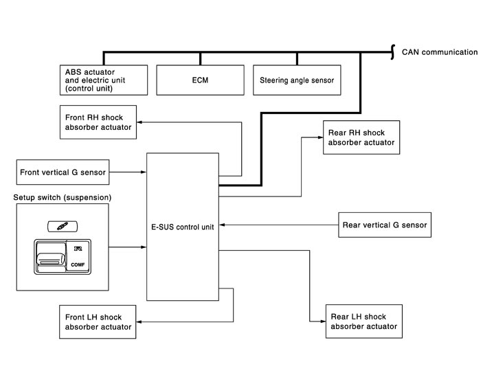
System Description
 Description
- The Bilstein DampTronic system mainly consists of the components such as the E-SUS control unit, front vertical G sensor, rear vertical G sensor, and shock absorber actuators on each wheel.
- It calculates the command values to be transmitted the shock absorber actuator on each wheel based on the information from ECM, ABS actuator and electric unit (control unit) and steering angle sensor and information from the front vertical G sensor and rear vertical G sensor via CAN communication.
- The shock absorber actuator on each wheel controls the damping force based on the command values calculated by E-SUS control unit.
- Can perform the self-diagnosis with CONSULT-III.
- Communicates the signal from each control unit via CAN communication.
Control unit Signal status Steering angle sensor Transmits mainly the following signals to E-SUS control unit via CAN communication. - Steering angle speed signal
ABS actuator and electric unit (control unit) Transmits mainly the following signals to E-SUS control unit via CAN communication. - Vehicle speed signal
- Brake pressure control signal
- Stop lamp switch signal
- ABS operation signal
- Side G sensor signal
ECM Transmits mainly the following signals to E-SUS control unit via CAN communication.
Engine speed signal - Steering angle speed signal
Operation principle- When the shutter is closedBecause the shutter (2) is closed (A) by the solenoid core (1), the maximum oil channel resistance and high damping force are obtained.

: Oil passage 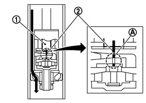
- When the shutter is openBecause the shutter (2) is opened (A) by the activated solenoid core (1) and the oil flows through 2 different passages, the minimum oil flow rate and low damping force are obtained.

: Shutter moving direction : Oil passage 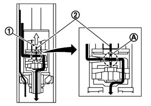
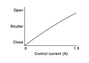
Operation characteristics- Changes the damping force range image of the shock absorber by switching the switch.
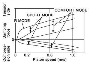
- Changes the damping force depending on the output current to the shock absorber actuators.
Component Parts Location
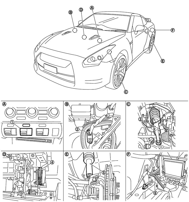
|
1. |
Set-up switch (suspension) |
2. |
Front vertical G sensor |
3. |
Front shock absorber (with integrated shock absorber actuator) |
|
4. |
E-SUS control unit |
5. |
Rear shock absorber (with integrated shock absorber actuator) |
6. |
Rear vertical G sensor |
|
A. |
Instrument center panel |
B. |
Right strut tower |
C. |
In front wheel well |
|
D. |
Rear of glove box |
E. |
In rear wheel well |
F. |
Trunk room left back |
Component Description
|
Component |
Reference/function |
|
E-SUS control unit |
Description (GT-R certified NISSAN dealer)
|
|
Front vertical G sensor |
Description (GT-R certified NISSAN dealer)
|
|
Rear vertical G sensor |
Description (GT-R certified NISSAN dealer)
|
|
Shock absorber actuator |
Description (GT-R certified NISSAN dealer)
|
|
Set-up switch (suspension) |
Description (GT-R certified NISSAN dealer)
|
|
Steering angle sensor |
Transmits the steering angle sensor signal to E-SUS control unit via CAN communication. |
|
ABS actuator and electric unit (control unit) |
Transmits mainly the following signal to E-SUS control unit via CAN communication.
|
|
ECM |
Transmits mainly the following signals to E-SUS control unit via CAN communication. Engine speed signal |