E-SUS CONTROL UNIT
Bilstein DampTronic
- Reference Value
- Wiring Diagram - Bilstein DampTronic SYSTEM -
- Fail-safe
- DTC Inspection Priority Chart
- DTC Index
Reference Value
 VALUES ON THE DIAGNOSIS TOOL
|
Monitor item |
Condition |
Value/Status | |
| VEHICLE SPEED | Vehicle stopped | 0 km/h (MPH) | |
| While driving for a time after the engine starts. ■ CAUTION ■ Check tire pressure in normal condition. | Almost in accordance with the speedometer display. (Within ±10%) | ||
| SIDE G-SENSOR | When stopped | Approx. 0 G | |
| At cornering | –2.0 – 2.0 G | ||
| ST ANGLE SPD | steering and holding | Approx. 0 deg/s | |
| Steering | 0 – 1000 deg/s | ||
| ESTIMATED TRQ |
| Approx. 4 – 20 Nm | |
| REQUESTED TRQ |
| Approx. 26 Nm | |
| ENGINE SPEED | Engine stop | 0 rpm | |
| Engine speed: 400 rpm or more | Almost in accordance with tachometer display (Within ±10%) | ||
| F G-SEN OUT VOL | When stopped | Approx. 2.23 – 2.77 V | |
| While driving | Approx. 0.95 – 4.2 V | ||
| R G-SEN OUT VOL | When stopped | Approx. 2.23 – 2.77 V | |
| While driving | Approx. 0.95 – 4.2 V | ||
| F G-SEN VOLTAGE | Always | Approx. 4.75 – 5.25 V | |
| R G-SEN VOLTAGE | Always | Approx. 4.75 – 5.25 V | |
| FR ACTUATOR CRNT | Vehicle stopped or R mode | 0 A | |
| While driving | Approx. 0 – 1.5 A | ||
| FL ACTUATOR CRNT | Vehicle stopped or R mode | 0 A | |
| While driving | Approx. 0 – 1.5 A | ||
| RR ACTUATOR CRNT | Vehicle stopped or R mode | 0 A | |
| While driving | Approx. 0 – 1.5 A | ||
| RL ACTUATOR CRNT | Vehicle stopped or R mode | 0 A | |
| While driving | Approx. 0 – 1.5 A | ||
| BATTERY VOLT | Always | Battery voltage | |
| MODE SW UP | UP operation | Approx. 1.34 – 2.08 – 2.79 V | |
| Neutral | Approx. 3.48 – 3.57 – 3.66 V | ||
| MODE SW DOWN | DOWN operation | Approx. 1.34 – 2.08 – 2.79 V | |
| Neutral | Approx. 3.48 – 3.57 – 3.66 V | ||
| BRK FLD PRESS | Brake deactivated | Approx. 0 bar | |
| Brake activated | –40 – 300 bar | ||
| STP LAMP SW | Depress the brake | On | |
| Do not depress the brake | Off | ||
| ABS SIGNAL | ABS is activated | On | |
| ABS is not activated | Off | ||
| FAIL MODE SIG | In fail-safe mode | On | |
| Normal | Off | ||
| R MODE LAMP | R mode | On | |
| Other than R mode | Off | ||
| CONF MODE LAMP | COMFORT mode | On | |
| Other than COMFORT mode | Off | ||
| IGN | Ignition switch: ON | On | |
| Ignition switch: OFF | Off | ||
| CONTROL MODE | R mode | R | |
| SPORT mode | SPORT | ||
| COMFORT mode | COMF | ||
TERMINAL LAYOUT PHYSICAL VALUES
|
Terminal No. (Wire color) |
Description |
Condition |
Value (Approx.) |
|||
|
+ |
- |
Signal name |
Input/Output |
|||
|
1 (P) |
— |
CAN-H |
— |
— |
— |
|
|
2 (P) |
Ground |
Set-up switch (suspension) up-side output voltage |
Output |
Set-up switch UP operation |
Approx. 1.34 – 2.08 – 2.79 V |
|
|
Set-up switch neutral |
Approx. 3.48 – 3.57 – 3.66 V |
|||||
|
3 (L) |
— |
CAN-L |
— |
— |
— |
|
|
4 (W) |
Ground |
Front vertical G sensor output voltage |
Input |
Ignition switch ON |
Approx. 2.35 – 2.65 V |
|
|
5 (O) |
— |
Set-up switch (suspension) R mode lamp voltage |
— |
— |
— |
|
|
6 (BR) |
Ground |
Rear vertical G sensor output voltage |
Input |
Ignition switch ON |
Approx. 2.35 – 2.65 V |
|
|
7 (R) |
Ground |
Set-up switch (suspension) down-side output voltage |
Output |
Set-up switch DOWN operation |
Approx. 1.34 – 2.08 – 2.79 V |
|
|
Set-up switch neutral |
Approx. 3.48 – 3.57 – 3.66 V |
|||||
|
8 (G) |
Ground |
Front vertical G sensor ground |
— |
Always |
0 V |
|
|
9 (LG) |
— |
Set-up switch (suspension) COMFORT mode lamp voltage |
— |
— |
— |
|
|
10 (R) |
— |
Front RH shock absorber actuator LOW terminal |
— |
— |
— |
|
|
11 (G) |
— |
Front RH shock absorber actuator HI terminal |
— |
— |
— |
|
|
12 (L) |
— |
Front LH shock absorber actuator LOW terminal |
— |
— |
— |
|
|
13 (G) |
Ground |
Rear vertical G sensor ground |
— |
Always |
0 V |
|
|
14 (SB) |
— |
Rear RH shock absorber actuator LOW terminal |
— |
— |
— |
|
|
15 (R) |
Ground |
Front vertical G sensor power supply |
Output |
Ignition switch ON |
Approx. 4.75 – 5.25 V |
|
|
16 (BR) |
— |
Rear LH shock absorber actuator HI terminal |
— |
— |
— |
|
|
17 (P) |
— |
Front LH shock absorber actuator HI terminal |
— |
— |
— |
|
|
18 (Y) |
— |
Rear LH shock absorber actuator LOW terminal |
— |
— |
— |
|
|
19 (R) |
Ground |
Ignition power supply |
Input |
Ignition switch: ON |
Battery voltage |
|
|
Ignition switch: OFF |
0 V |
|||||
|
20 (V) |
— |
Rear RH shock absorber actuator HI terminal |
— |
— |
— |
|
|
21 (R) |
Ground |
Rear vertical G sensor power supply |
Output |
Ignition switch ON |
Approx. 4.75 – 5.25 V |
|
|
22 (B) |
Ground |
Ground |
— |
Always |
0 V |
|
|
23 (L) |
Ground |
E-SUS control unit power supply |
Input |
Always |
Battery voltage |
|
Wiring Diagram - Bilstein DampTronic SYSTEM -
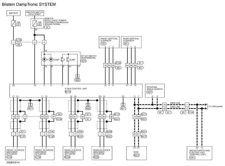
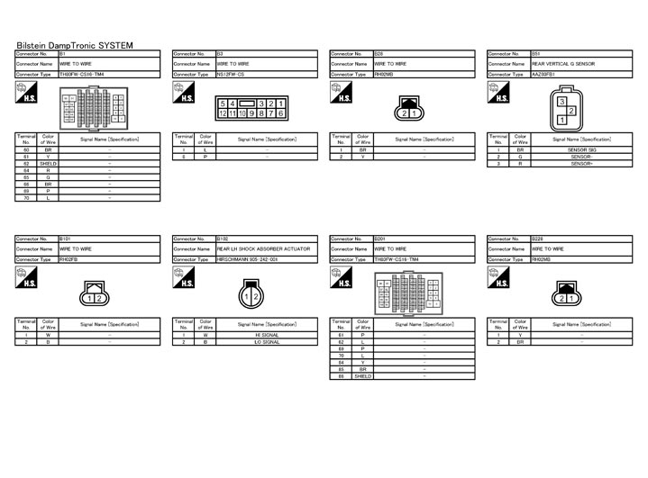
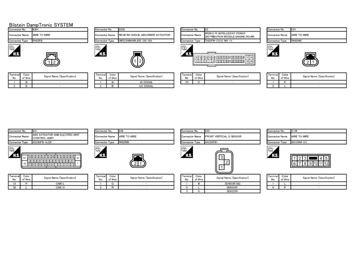
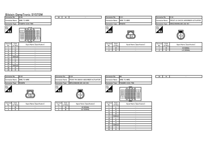
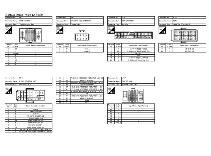
Fail-safe
Bilstein DampTronic system- When detecting any malfunction in each component of the system, it enters the fail-safe status (the Bilstein DampTronic system control is deactivated).
- At the same time when the system enters the control stop status, it becomes the equivalent status to R mode (fixed damping status).
- Even if the set-up switch (suspension) is operated in the fail-safe status, no lamp illuminates in R mode or COMFORT mode.
DTC Inspection Priority Chart
When multiple DTCs are detected simultaneously, check one by one depending on the following priority list.
| Priority | Priority order item (DTC) |
| 1 |
|
| 2 | Other than the above |