SUSPENSION ARM
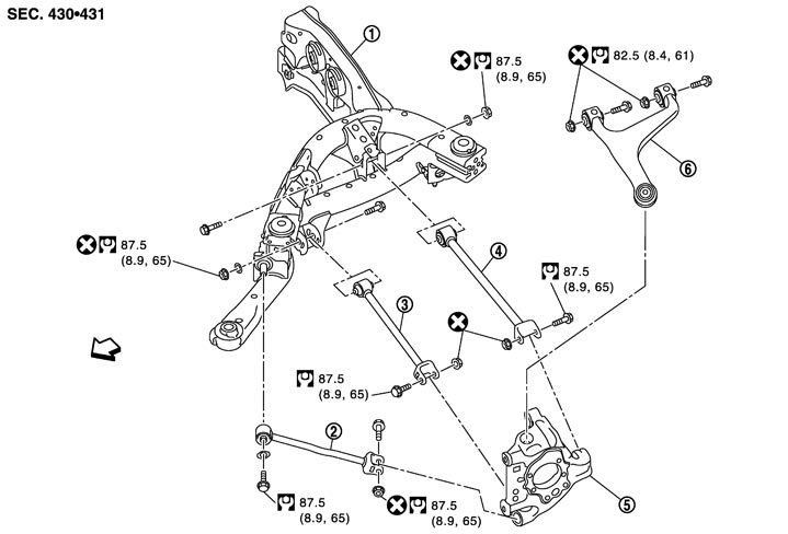
Exploded View
|
1. |
Rear suspension member |
2. |
Radius rod |
3. |
Front lower link |
|
4. |
Rear lower link |
5. |
Axle housing |
6. |
Suspension arm |
 : Vehicle front : Vehicle front |
|
|
|
|
|
|
Refer to Components for the symbols in the figure. |
|||||
Removal and Installation
 REMOVAL
- 1.Remove tire with power tool.
- 2.Remove brake hose bracket. Refer to Exploded View.
- 3.Remove caliper assembly mounting bolts. Hang caliper assembly in a place where it will not interfere with work. Refer to Exploded View (GT-R certified NISSAN dealer).
- 4.Remove disc rotor. Refer to Removal and Installation (GT-R certified NISSAN dealer).
- 5.Set suitable jack under axle assembly.
- 6.Separate shock absorber from axle housing. Refer to Exploded View.
- 7.Remove cotter pin of suspension arm ball joint, and loosen nut. Refer to Exploded View.
- 8.Remove suspension arm mounting bolts and nuts from rear suspension member.
- 9.Remove suspension arm from axle housing. Refer to Exploded View.
- 10.Remove suspension arm.
INSTALLATIONNote the following and, install in the reverse order of removal.
- Perform final tightening of bolts and nuts at the vehicle installation position (rubber bussing), under unladen conditions with tires on level ground.
- Never reuse cotter pin.
Inspection
INSPECTION AFTER REMOVAL (PILLOW BALL BUSHING) Appearance
Check the following items, and replace the part if necessary.
- Ball stud boot for cracks, damage or leakage of grease.
- Suspension arm and ball stud for deformation, cracks or damage.
Ball stud InspectionManually move ball stud to check that it moves smoothly with no binding and check for looseness. Replace the suspension arm if necessary.
Swing Torque Inspection- 1.Move the ball stud ten times or more by hand to check for smooth movement.
- 2.Hook spring balance at the ball stud inner cylinder. Check that the reading at the moment that the ball stud begins moving is within the standard.
- If swing torque outside standard range, replace suspension arm assembly.
| Standard | |
| Swing torque | : Refer to Ball Joint (GT-R certified NISSAN dealer). |
| Measurement on spring balance | : Refer to Ball Joint (GT-R certified NISSAN dealer). |
INSPECTION AFTER REMOVAL (BALL JOINT) AppearanceCheck the following items, and replace the part if necessary
- Suspension arm and ball joint for deformation, cracks or damage.
- Ball joint boot for cracks, damage or leakage of grease.
Ball Joint InspectionManually move ball joint to check that it moves smoothly with no binding and check for looseness. Replace the suspension arm if necessary.
Swing Torque Inspection- 1.Move the ball joint ten times or more by hand to check for smooth movement.
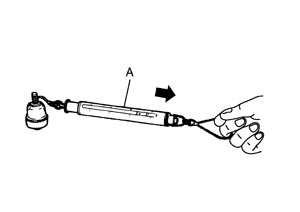
- 2.Hook spring balance (A) at cotter pin mounting hole. Check that the reading at the moment that the ball stud begins moving is within the standard.
- If swing torque outside standard range, replace suspension arm assembly.
| Standard | |
| Swing torque | : Refer to Ball Joint (GT-R certified NISSAN dealer). |
Rotating Torque Inspection- 1.Move the ball joint ten times or more by hand to check for smooth movement.
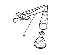
- 2.Install the mounting nut to ball joint. Check that rotating torque is within the standard with a preload gauge (A) [SST: ST3127S000 (J-25765-A)].
- If rotating torque outside standard range, replace the suspension arm assembly.
| Standard | |
| Rotating torque | : Refer to Ball Joint (GT-R certified NISSAN dealer). |
Axial End Play InspectionMove tip of ball joint in axial direction to check looseness.
| Standard | |
| Axial end play | : Refer to Ball Joint (GT-R certified NISSAN dealer). |
- If axial end play outside standard range, replace the suspension arm assembly.
INSPECTION AFTER INSTALLATION- 1.Check wheel alignment. Refer to Wheel Alignment.
- 2.Adjust neutral position of steering angle sensor. Refer to Special Repair Requirement (GT-R certified NISSAN dealer).