BRAKE PEDAL
Exploded View
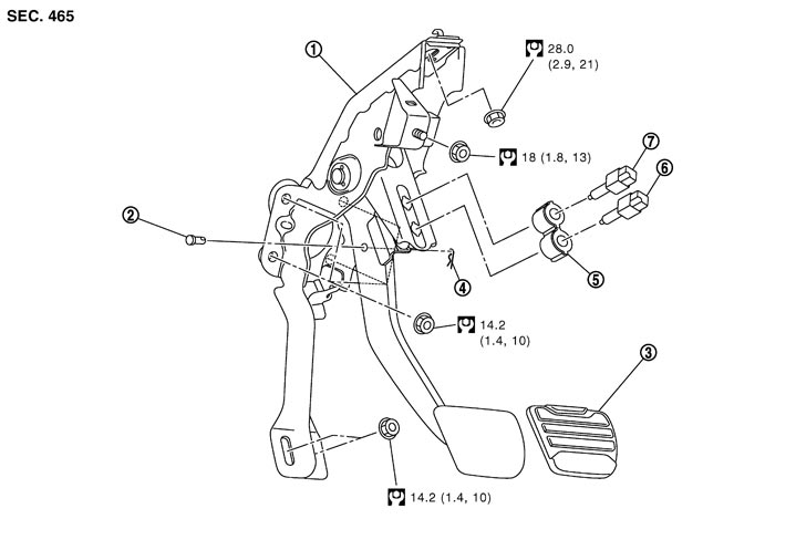
|
1. |
Brake pedal assembly |
2. |
Clevis pin |
3. |
Brake pedal pad |
|
4. |
Snap pin |
5. |
Clip |
6. |
Stop lamp switch |
|
7. |
ASCD brake switch |
|
|
|
|
|
Refer to Components for the symbols in the figure. |
|||||
Removal and Installation
 REMOVAL
- 1.Remove instrument lower panel (driver). Refer to Exploded View.
- 2.Remove the footrest. Refer to Exploded View.
- 3.Remove the kicking plate inner, dash side finisher and floor trim. Refer to Exploded View, Exploded View.
- 4.Disconnect the harness connectors of ASCD brake switch and stop lamp switch.
- 5.Rotate ASCD brake switch and stop lamp switch counterclockwise to remove.
- 6.Remove the snap pin, and then remove the clevis pin from the clevis of brake booster.
- 7.Remove the brake pedal assembly.
INSTALLATIONInstall in the reverse order of removal.
Inspection and Adjustment
INSPECTION AFTER REMOVALCheck the following items and replace the brake pedal assembly if necessary.
- Check the brake pedal for bend, damage, or cracks on the welded parts.
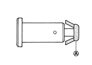
- Check clevis pin and plastic stopper (A) for damage or deformation. If any damage is found, replace clevis pin.
ADJUSTMENT AFTER INSTALLATION- Adjust each item of brake pedal after installing the brake pedal assembly to the vehicle. Refer to Inspection and Adjustment.
- Perform the release position learning of the accelerator pedal. Refer to Special Repair Requirement (GT-R certified NISSAN dealer).