BRAKE MASTER CYLINDER
Exploded View
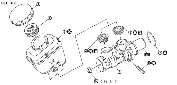
|
1. |
Reservoir cap |
2. |
Oil strainer |
3. |
Reservoir tank |
|
4. |
Grommet |
5. |
Cylinder body |
6. |
Pin |
|
7. |
O-ring |
|
|
|
|
 : Apply polyglycol ether based lubricant. : Apply polyglycol ether based lubricant. |
|||||
 : Brake fluid : Brake fluid |
|||||
|
Refer to Components for symbols not described on the above. |
|||||
Removal and Installation
 REMOVAL
■ CAUTION ■
Never spill or splash brake fluid on painted surfaces. Brake fluid may seriously damage paint. Wipe it out immediately and wash with water if it gets on a painted surface.
- 1.Remove the brake master cylinder cover and hood ledge cover LH. Refer to Exploded View.
- 2.Drain brake fluid. Refer to Draining.
- 3.Separate the brake fluid level switch harness connector.
- 4.Separate the brake tube from the master cylinder assembly with a flare nut wrench.
■ CAUTION ■
Never scratch the flare nut and the brake tube.- 5.Depress the brake pedal several times to release the vacuum pressure from the brake booster. Then remove the master cylinder assembly.
- Never depress the brake pedal after the master cylinder assembly is removed.
- The piston of the master cylinder assembly is exposed. Never damage it when removing the master cylinder.
- The piston may drop off when pulled out strongly. Never hold the piston. Hold the cylinder body when handling the master cylinder assembly.
■ CAUTION ■
INSTALLATION■ CAUTION ■
Never spill or splash brake fluid on painted surfaces. Brake fluid may seriously damage paint. Wipe it out immediately and wash with water if it gets on a painted surface.
Note the following, and install in the reverse order of removal.
- Never depress the brake pedal after the master cylinder assembly is removed.
- Never reuse the O-ring.
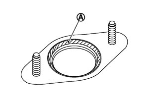
- Apply polyglycol ether based lubricant to the brake booster [see (A) in the figure] when installing the master cylinder assembly to the brake booster.
- The piston of the master cylinder assembly is exposed. Never damage it when handling the master cylinder and check that no dirt and dust are present on the piston before installation. Clean it with new brake fluid if necessary.
- The piston may drop off when pulled strongly. Never hold the piston. Hold the cylinder body when handling the master cylinder assembly.
- Temporarily tighten the brake tube flare nut to the master cylinder assembly by hand. Then tighten it to the specified torque with a flare nut crowfoot and torque wrench. Refer to Exploded View.■ CAUTION ■Never scratch the flare nut and the brake tube.
- After installation, perform the air bleeding. Refer to Bleeding Brake System.■ CAUTION ■Never reuse drained brake fluid.
Disassembly and Assembly
DISASSEMBLY■ CAUTION ■
- Never disassemble the cylinder body.
- Remove the reservoir tank only when necessary.
- 1.Fix the master cylinder assembly to a vise.
- Always set copper plates or cloth between vise jaws when fixing the cylinder body to a vise.
- Never overtighten the vise.
■ CAUTION ■
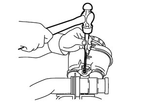
- 2.Remove the reservoir tank mounting pin with a pin punch.
- 3.Remove the reservoir tank and grommet from the cylinder body.
■ CAUTION ■
Never drop the removed parts. The parts must not be reused if they are dropped. ASSEMBLY■ CAUTION ■
- Never use mineral oils such as kerosene or gasoline and rubber grease during the cleaning and assembly process.
- Never drop the parts when installing. The parts must not be reused if they are dropped.
- 1.Apply new brake fluid to the grommet and install it to the cylinder body.
■ CAUTION ■
Never reuse grommet.- 2.Install the reservoir tank to the cylinder body.
- 3.Fix the cylinder body to a vise.
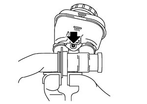
- Place the reservoir tank with the chamfered pin hole (
 ) facing up.
 - Always set copper plates or cloth between vise jaws when fixing the cylinder body to a vise.
- Never overtighten the vise.
■ CAUTION ■
- 4.Tilt the reservoir tank so that a mounting pin can be inserted. Insert a mounting pin. Return the reservoir tank to the horizontal position. Insert another mounting pin into the pin hole on the opposite side in the same manner after the mounting pin passes through the cylinder body pin hole.
■ CAUTION ■
Never reuse pin.Inspection
INSPECTION AFTER INSTALLATION- Check for fluid leakage from connections, damage, twists, deformation or contact with other parts. Replace if necessary. ■ CAUTION ■If the looseness of connection or fluid leakage is present, retighten to the specified torque. Replace if necessary.
- Depress the brake pedal with a force of 785 N (80 kg, 176 lb) and hold down the pedal for approximately 5 seconds with the engine running. Check for any fluid leakage.