BRAKE BOOSTER
Exploded View
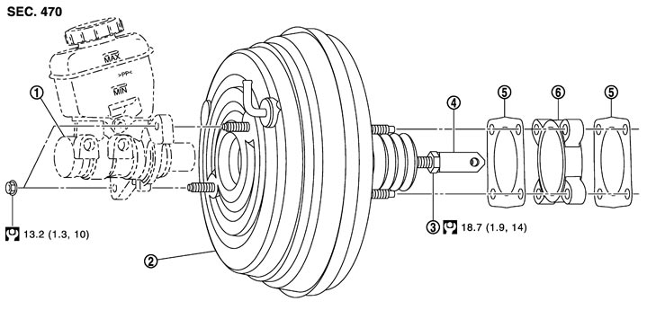
|
1. |
Master cylinder assembly |
2. |
Brake booster |
3. |
Lock nut |
|
4. |
Clevis |
5. |
Gasket |
6. |
Spacer |
|
Refer to Components for the symbols in the figure. |
|||||
Removal and Installation
 REMOVAL
- 1.Remove the brake master cylinder cover and hood ledge cover LH. Refer to Exploded View.
- 2.Remove cowl top cover. Refer to Exploded View.
- 3.Remove master cylinder. Refer to Exploded View (GT-R certified NISSAN dealer).
- Depress the brake pedal several times to release the vacuum pressure from the brake booster. Then remove the master cylinder assembly.
- Never depress the brake pedal after the master cylinder assembly is removed.
- The piston of the master cylinder assembly is exposed. Never damage it when removing the master cylinder.
- The piston may drop off when pulled out strongly. Never hold the piston. Hold the cylinder body when handling the master cylinder assembly.
■ CAUTION ■
- 4.Remove vacuum hose from brake booster. Refer to Exploded View (GT-R certified NISSAN dealer).
- 5.Remove snap pin (1) and clevis pin (2).
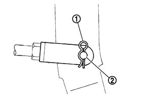
- 6.Disconnect the brake tube from the ABS actuator electric unit (control unit). Refer to Exploded View.
- 7.Remove the clip from the brake tube. Refer to Exploded View.
- 8.Remove the brake tube [between ABS actuator electric unit (control unit) and master cylinder]. Refer to Exploded View.
- 9.Remove the relay box and bracket.
- 10.Remove brake booster, spacer and gasket.
■ CAUTION ■
Never deform or bend the brake tubes. INSTALLATIONNote the following, and install in the reverse order of removal.
- Be careful not to damage brake booster stud bolt threads. If brake booster is tilted during installation, the dash panel may damage the threads.
- Never deform or bend the brake tubes when installing the brake booster.
- Always use a new gasket between the brake booster and the dash panel.
- Replace the clevis pin if it is damaged. Refer to Inspection and Adjustment (GT-R certified NISSAN dealer).
- After installation, perform the air bleeding. Refer to Bleeding Brake System.■ CAUTION ■Never reuse drained brake fluid.
Inspection and Adjustment
ADJUSTMENT AFTER REMOVAL Input Rod Length adjustment
- 1.Loosen the lock nut (1) and adjust the input rod (2) to the specified length (A).
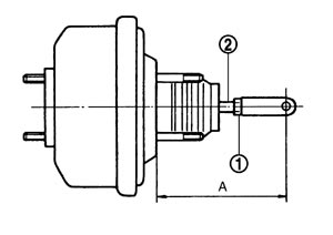
| Standard | |
| A | : Refer to Brake Booster (GT-R certified NISSAN dealer). |
- 2.Tighten the lock nut to the specified torque.
INSPECTION AFTER INSTALLATION OperationDepress the brake pedal several times at 5-second intervals with the engine stopped. Start the engine with the brake pedal fully depressed. Check that the clearance between brake pedal and dash lower pane decreases.
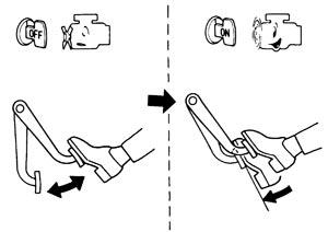
NOTE:
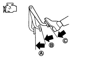
A slight impact with a small click may be felt on the pedal when the brake pedal is fully depressed. This is a normal phenomenon due to the brake system operation. Air Tight- Idle the engine for 1 minute to apply vacuum to the brake booster, and stop the engine. Then depress the brake pedal several times at 5-second intervals until the accumulated vacuum is released to atmospheric pressure. Check that the clearance between brake pedal and dash lower panel gradually increases (A → B → C) each time the brake pedal is depressed when performing this operation.
- Depress the brake pedal with the engine running. Then stop the engine while holding down the brake pedal. Check that the brake pedal stroke does not change after holding down the brake pedal for 30 seconds or more.
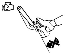 NOTE:A slight impact with a small click may be felt on the pedal when the brake pedal is fully depressed. This is a normal phenomenon due to the brake system operation.
ADJUSTMENT AFTER INSTALLATIONPerform the brake pedal adjustment after installing the brake pedal assembly. Refer to Inspection and Adjustment.