VACUUM LINES
Exploded View
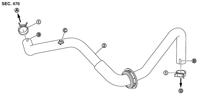
|
1. |
Clamp |
2. |
Vacuum hose (built in check valve) |
|
|
|
A. |
To intake manifold |
B. |
Paint mark |
C. |
Stamp indicating engine direction |
|
D. |
To brake booster |
|
|
|
|
Removal and Installation
 REMOVAL INSTALLATION
Note the following, install in the reverse order of removal.
- Because vacuum hose contains a check valve, it must be installed in the correct position. Refer to the stamp to confirm correct installation. Brake booster will not operate normally if the hose is installed in the wrong direction.
- When installing vacuum hose, insert it until its tip reaches the back-end of the length (A) or further as shown in the figure.
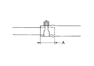
Standard A : 24 mm (0.95 in) or more - Face the marking side vehicle front when assembling. (Brake booster side)
- Face the marking side up when assembling. (Intake manifold side)
■ CAUTION ■
Never use lubricating oil during assembly.Inspection
INSPECTION AFTER REMOVAL Appearance
Check for correct assembly, damage and deterioration.
Check Valve Airtightness- Use a handy vacuum pump (A) to check.
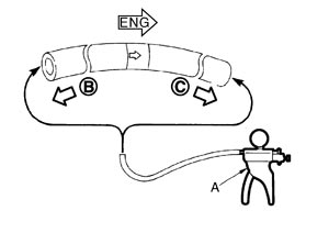
When connected to the booster side (B): Vacuum must be decrease within 1.3 kPa (9.8 mmHg, 0.38 inHg) for 15 seconds under a vacuum of −66.7 kPa (−500 mmHg, −19.69 inHg). When connected to the engine side (C): Vacuum must be not exist. - Replace vacuum hose assembly if vacuum hose and check valve are malfunctioning.