PARKING BRAKE SHOE
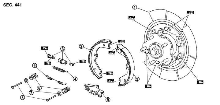
Exploded View
|
1. |
Back plate |
2. |
Parking brake shoe |
3. |
Adjuster |
|
4. |
Adjuster spring |
5. |
Return spring |
6. |
Anti-rattle spring |
|
7. |
Retainer |
8. |
Anti-rattle pin |
9. |
Toggle lever |
 : Apply PBC (Poly Butyl Cuprysil) grease or silicone-based grease. : Apply PBC (Poly Butyl Cuprysil) grease or silicone-based grease. |
|||||
Removal and Installation
 REMOVAL
■ WARNING ■
Clean any dust from the parking brake shoes and back plates with a vacuum dust collector. Never blow with compressed air.
- 1.Remove rear tires with power tool.
- 2.Remove the disc rotor with the parking brake lever returned. Refer to Removal and Installation.If disc rotor cannot be removed, remove as follows:
-
(1)Fix the disc rotor using wheel nuts.
-
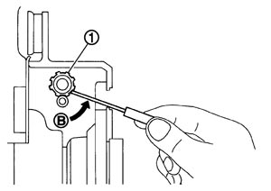
(2)Remove the adjusting hole plug from the disc rotor, rotate the adjuster (1) in the direction (B) using a suitable tool, and then compress the expanded brake shoe.
- 3.Rotate the anti-rattle pins while pressing them, and then remove the anti-rattle pins, retainers and anti-rattle springs from the back plate.
■ CAUTION ■
Never drop the removed parts.- 4.Remove adjuster spring and return spring.
■ CAUTION ■
Never drop the removed parts.- 5.Remove parking brake shoes, adjuster assembly and toggle lever.
- The parking brake shoes for the vehicle front side are made of different materials from those for the vehicle rear side. Never misidentify them when removing.
- Never drop the removed parts.
■ CAUTION ■
- 6.When removing the brake plate, refer to Exploded View.
INSTALLATIONNote the following, install in the reverse order of removal.
- Apply PBC (Poly Butyl Cuprysil) grease or silicone-based grease to the back plate and brake shoe.■ CAUTION ■The parking brake shoes for the vehicle front side are made of different materials from those for the vehicle rear side. Never misidentify them when removing.
- Assemble adjusters so that the threaded part is expanded when rotating it in the direction shown by the arrow.
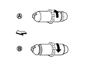
A: For right side brake B: For left side brake  : Vehicle front
 : Adjuster expands
 - Shorten adjuster by rotating it.
- When disassembling apply PBC (Poly Butyl Cuprysil) grease or silicone-based grease to threads.
- Check brake shoe sliding surface and drum inner surface for grease. Wipe it out any adheres to the surfaces.
- Perform the break-in operations after finishing the installation. Refer to Adjustment.
Inspection
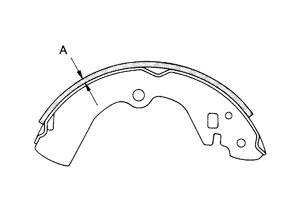
INSPECTION AFTER REMOVAL Lining Thickness Inspection
 Drum Inner Diameter Inspection
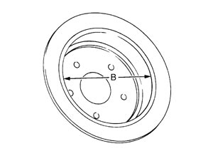 Other Inspections
Check the following items, and replace the parts if necessary.
- Lining for excessive wear, damage or peeling.
- Brake shoe sliding surface for excessive wear or damage.
- Anti-rattle pin and retainer for excessive wear, damage or rust.
- Adjuster spring, return spring and anti-rattle spring for settling, excessive wear, damage or rust.
- Adjuster for smoothness.
- Toggle lever for excessive wear, damage or rust.
- Visually check inside of the drum for excessive wear, cracks or damage with a pair of vernier calipers.
ADJUSTMENT AFTER INSTALLATIONCheck the parking brake for drag. Perform the following procedure if necessary.
- 1.Adjust the parking brake lever stroke. Refer to Inspection and Adjustment.
- 2.Check the parking brake for drag again. Check the rear disc brake for drag if necessary. Refer to Inspection.