SECONDARY AIR INJECTION SYSTEM
VR38
System Diagram
System Description
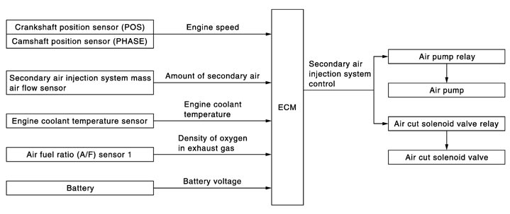
 INPUT/OUTPUT SIGNAL CHART
|
Sensor |
Input signal to ECM |
ECM function |
Actuator |
|
Crankshaft position sensor (POS) Camshaft position sensor (PHASE) |
Engine speed |
Secondary air injection system control |
|
|
Secondary air injection system mass air flow sensor |
Amount of secondary air |
||
|
Engine coolant temperature sensor |
Engine coolant temperature |
||
|
Air fuel ratio (A/F) sensor 1 |
Density of oxygen in exhaust gas |
||
|
Battery |
Battery voltage |
SYSTEM DESCRIPTION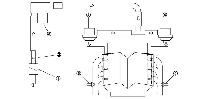
|
1. |
Air pump cleaner |
2. |
Secondary air injection system mass air flow sensor |
3. |
Air pump |
|
4. |
Air cut solenoid valve |
5. |
Air fuel ratio sensor 1 |
|
|

|
: Secondary air |
|
|
|
|
During a cold start, the secondary air injection system supplies the air to the engine exhaust port so that the CO and HC burns and an increase in the temperature of the three way catalyst is facilitated. The three way catalyst is quickly activated and the emission gas during the cold start is reduced. When all of the following conditions are satisfied, the ECM activates the air pump, opens the air cut solenoid valve and supplies the secondary air to the exhaust port. The secondary air injection system operates for approximately a few tenths of a second depending on the engine coolant temperature and other conditions. When the system is deactivated, the ECM closes the air cut solenoid valve and stops the air pump to prevent the emission gas from blowing back.
< Activating conditions >
- When starting the engine
- Battery voltage: More than 10 V
- Engine coolant temperature at engine start is between 15 - 35 °C (59 - 95° F) and has lowered 45°C (113° F) or more since the latest engine stop.
SECONDARY AIR INJECTION SYSTEM LINE DRAWING
|
1. |
Air pump cleaner |
2. |
Air cut solenoid valve (bank 1) |
3. |
Air cut solenoid valve (bank 2) |
|
4. |
Air pump |
5. |
Secondary air injection system mass air flow sensor |
|
|
|
: Vehicle front |
|||||
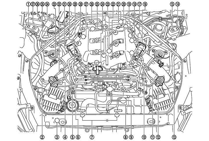
Component Parts Location
|
1. |
Air cut solenoid valve relay |
2. |
Recirculation valve (bank 1) |
3. |
Refrigerant pressure sensor |
|
4. |
Mass air flow sensor (with intake air temperature sensor) (bank 1) |
5. |
Power steering pressure sensor |
6. |
EVAP canister purge volume control solenoid valve |
|
7. |
Cooling fan motor |
8. |
Cooling fan control module |
9. |
Intake valve timing control solenoid valve |
|
10. |
Turbocharger boost control solenoid valve |
11. |
Mass air flow sensor (with intake air temperature sensor) (bank 2) |
12. |
Recirculation valve (bank 2) |
|
13. |
Turbocharger boost sensor (bank 2) |
14. |
Cooling fan relay-1 |
15. |
Cooling fan relay-2 |
|
16. |
Electric throttle control actuator (bank 2) |
17. |
Ignition coil (with power transistor) and spark plug (bank 2) |
18. |
Camshaft position sensor (PHASE) (bank 2) |
|
19. |
Air cut solenoid valve (bank 2) |
20. |
Crankshaft position sensor (POS) |
21. |
Fuel injector (bank 2) |
|
22. |
Knock sensor |
23. |
Engine oil temperature sensor |
24. |
Fuel injector (bank 1) |
|
25. |
Engine coolant temperature sensor |
26. |
A/F sensor 1 (bank 1) |
27. |
Camshaft position sensor (PHASE) (bank 1) |
|
28. |
Air cut solenoid valve (bank 1) |
29. |
Manifold absolute pressure sensor |
30. |
Ignition coil (with power transistor) and spark plug (bank 1) |
|
31. |
Electric throttle control actuator (bank 1) |
32. |
EVAP service port |
33. |
Turbocharger boost sensor (bank 1) |
|
34. |
IPDM E/R |
35. |
Air pump cleaner |
36. |
Air pump |
|
37. |
Air pump relay |
|
|
|
|
|
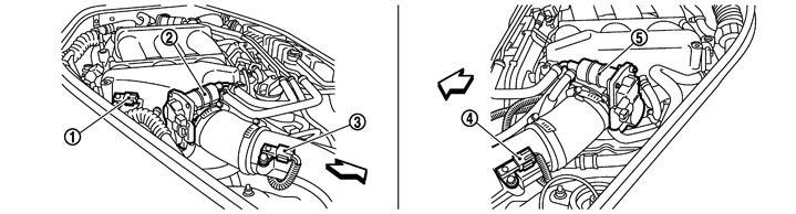
1. |
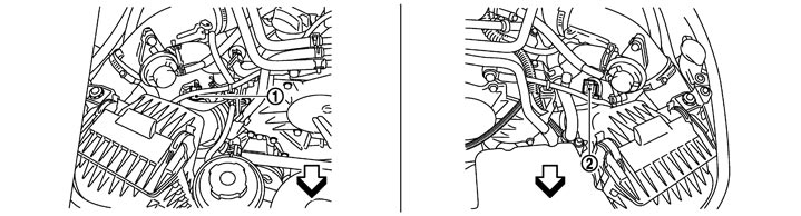
Mass air flow sensor (with intake air temperature sensor) (bank 1) |
2. |
Mass air flow sensor (with intake air temperature sensor) (bank 2) |
|
|
|
|
:Vehicle front |
|
|
|
|
|
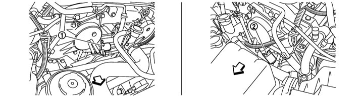
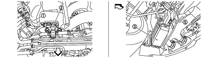
1. |
Manifold absolute pressure sensor |
2. |
Electric throttle control actuator (bank 1) |
3. |
Turbocharger boost sensor (bank 1) |
|
4. |
Turbocharger boost sensor (bank 2) |
5. |
Electric throttle control actuator (bank 2) |
|
|
|
|
:Vehicle front |
|
|
|
|
|
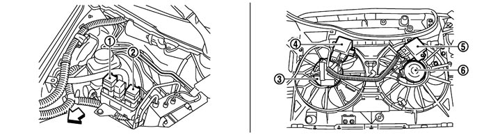
1. |
Intake valve timing control solenoid valve (bank1) |
2. |
Intake valve timing control solenoid valve (bank2) |
|
|
|
|
:Vehicle front |
|
|
|
|
|
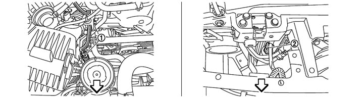
1. |
Cooling fan relay-2 |
2. |
Cooling fan relay-1 |
3. |
Cooling fan motor-1 |
|
4. |
Cooling fan control module-1 |
5. |
Cooling fan control module-2 |
6. |
Cooling fan motor-2 |
|
|
:Vehicle front |
|
|
|
|
|
1. |
Power steering pressure sensor |
2. |
Refrigerant pressure sensor |
|
|
|
|
:Vehicle front |
|
|
|
|
|
1. |
EVAP service port |
2. |
EVAP canister purge volume control solenoid valve |
3. |
EVAP canister |
|
4. |
EVAP control system pressure sensor |
5. |
EVAP canister vent control valve |
|
|
|
|
:Vehicle front |
|
|
|
|
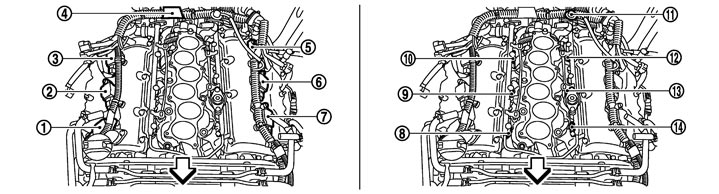
|
1. |
Ignition coil No.1 (with power transistor) |
2. |
Ignition coil No.3 (with power transistor) |
3. |
Ignition coil No.5 (with power transistor) |
|
4. |
Condenser |
5. |
Ignition coil No.6 (with power transistor) |
6. |
Ignition coil No.4 (with power transistor) |
|
7. |
Ignition coil No.2 (with power transistor) |
8. |
Fuel injector No.1 |
9. |
Fuel injector No.3 |
|
10. |
Fuel injector No.5 |
11. |
Fuel pressure regulator |
12. |
Fuel injector No.6 |
|
13. |
Fuel injector No.4 |
14. |
Fuel injector No.2 |
|
|
|
|
:Vehicle front |
|
|
|
|
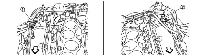
|
1. |
Camshaft position sensor (PHASE) (bank 1) |
2. |
Camshaft position sensor (PHASE) (bank 2) |
|
|
|
|
:Vehicle front |
|
|
|
|
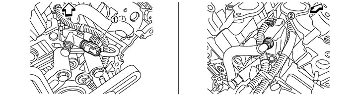
|
1. |
Engine oil temperature sensor |
2. |
PCV valve |
|
|
|
|
:Vehicle front |
|
|
|
|
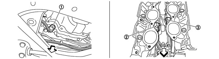
|
1. |
Crankshaft position sensor (POS) |
2. |
Knock sensor (bank1) |
3. |
Knock sensor (bank2) |
|
|
:Vehicle front |
|
|
|
|
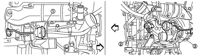
|
1. |
Boost control actuator (bank1) |
2. |
Turbocharger boost control solenoid valve |
3. |
Boost control actuator (bank2) |
|
|
:Vehicle front |
|
|
|
|
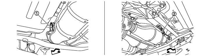
|
1. |
Heated oxygen sensor 2 (bank 2) |
2. |
Heated oxygen sensor 2 (bank 1) |
|
|
|
|
:Vehicle front |
|
|
|
|
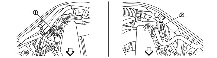
|
1. |
A/F sensor 1 (bank 1) harness connector |
2. |
A/F sensor 1 (bank 2) harness connector |
|
|
|
|
:Vehicle front |
|
|
|
|
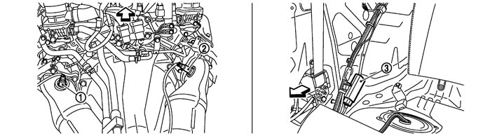
|
1. |
A/F sensor 1 (bank 2) |
2. |
A/F sensor 1 (bank 1) |
3. |
Fuel pump control module (FPCM) |
|
|
:Vehicle front |
|
|
|
|
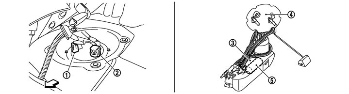
|
1. |
Sub fuel pump harness connector |
2. |
Main fuel gauge fuel filter fuel pump assembly harness connector |
3. |
Sub fuel pump |
|
4. |
Main fuel gauge fuel filter fuel pump assembly |
5. |
Fuel pump |
|
|
|
|
:Vehicle front |
|
|
|
|
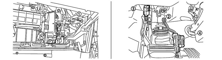
|
1. |
ECM |
2. |
Brake switch |
3. |
Stop lamp switch |
|
4. |
Accelerator pedal position sensor |
|
|
|
|
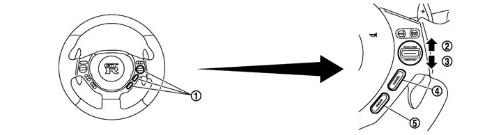
|
1. |
ASCD steering switch |
2. |
RESUME/ACCELERATE switch |
3. |
SET/COAST switch |
|
4. |
CANCEL switch |
5. |
MAIN switch |
|
|
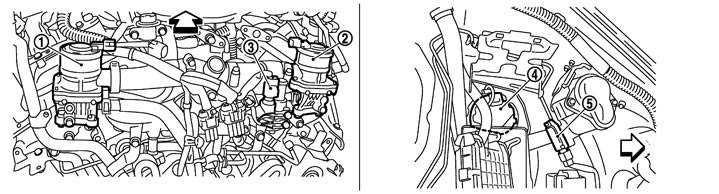
|
1. |
Air cut solenoid valve (bank 2) |
2. |
Air cut solenoid valve (bank 1) |
3. |
Engine coolant temperature sensor |
|
4. |
Air pump |
5. |
Secondary air injection system mass air flow sensor |
|
|
|
|
:Vehicle front |
|
|
|
|

|
1. |
Air cut solenoid valve relay |
2. |
Air pump relay |
3. |
Air pump cleaner |
|
4. |
IPDM E/R |
|
|
|
|
Component Description
|
Component |
Reference |
|
A/F sensor 1 |
Description (GT-R certified NISSAN dealer)
|
|
Air cut solenoid valve |
Description (GT-R certified NISSAN dealer)
|
|
Camshaft position sensor (PHASE) |
Description (GT-R certified NISSAN dealer)
|
|
Crankshaft position sensor (POS) |
Description (GT-R certified NISSAN dealer)
|
|
Engine coolant temperature sensor |
Description (GT-R certified NISSAN dealer)
|
|
Secondary air injection system mass air flow sensor |
Description (GT-R certified NISSAN dealer)
|