Nissan GT-R (R35) · Service Manual ENGINE

P0236, P0240 TC BOOST SENSOR

VR38

P0236 P0240

Description


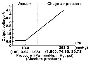
The turbocharger boost sensor detects the pressure of the outlet side of the intercooler. When increasing the pressure, the output voltage of the sensor to the ECM increases.
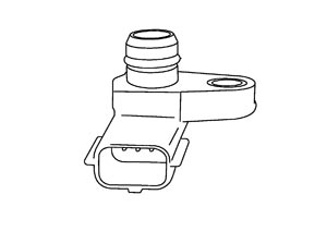
JMBIA0877ZZ.JPG


JMBIA1453GB.JPG

DTC Logic

 
 DTC DETECTION LOGIC

If DTC P0236 or P0240 is displayed with DTC P0643, first perform the trouble diagnosis for DTC P0643.
Refer to DTC Logic (GT-R certified NISSAN dealer).

DTC No.
Trouble diagnosis name
DTC detecting condition
Possible cause
P0236
Turbocharger boost sensor circuit range/performance (bank 1)
A
In spite of the low boost, the signal voltage of the turbocharger boost sensor to the ECM is too high.
  • Harness or connectors
    (The sensor circuit is shorted.)
  • Turbocharger boost sensor
  • Boost control actuator stuck closed
B
In spite of the high boost, the signal voltage of the turbocharger boost sensor to the ECM is too low.
  • Harness or connectors
    (The sensor circuit is open.)
  • Intake air leaks
  • Exhaust gas leaks
  • Recirculation valve
  • Exhaust manifold and Turbocharger assembly
  • Turbocharger boost sensor
  • Boost control actuator
P0240
Turbocharger boost sensor circuit range/performance (bank 2)
A
In spite of the low boost, the signal voltage of the turbocharger boost sensor to the ECM is too high.
  • Harness or connectors
    (The sensor circuit is shorted.)
  • Turbocharger boost sensor
  • Boost control actuator stuck closed
B
In spite of the high boost, the signal voltage of the turbocharger boost sensor to the ECM is too low.
  • Harness or connectors
    (The sensor circuit is open.)
  • Intake air leaks
  • Exhaust gas leaks
  • Recirculation valve
  • Exhaust manifold and Turbocharger assembly
  • Turbocharger boost sensor
  • Boost control actuator

 
 DTC CONFIRMATION PROCEDURE

 
 1.PRECONDITIONING
 
 2.PERFORM DTC CONFIRMATION PROCEDURE
 
 3.PERFORM COMPONENT FUNCTION CHECK

Component Function Check


 1.PERFORM COMPONENT FUNCTION CHECK

Diagnosis Procedure


 1.CHECK FOR EXHAUST GAS LEAK
 
 2.CHECK FOR INTAKE AIR LEAK
 
 3.CHECK GROUND CONNECTION
 
 4.CHECK TURBOCHARGER BOOST SENSOR POWER SUPPLY CIRCUIT
 
 5.CHECK TURBOCHARGER BOOST SENSOR GROUND CIRCUIT FOR OPEN AND SHORT
 
 6.CHECK TURBOCHARGER BOOST SENSOR INPUT SIGNAL CIRCUIT FOR OPEN AND SHORT
 
 7.CHECK TURBOCHARGER BOOST SENSOR
 
 8.CHECK RECIRCULATION VALVE
 
 9.CHECK EXHAUST MANIFOLD AND TURBOCHARGER ASSEMBLY
 
 10.CHECK INTERMITTENT INCIDENT

Component Inspection


 1.CHECK TURBOCHARGER BOOST SENSOR