FRONT WIPER AND WASHER SYSTEM
System Diagram
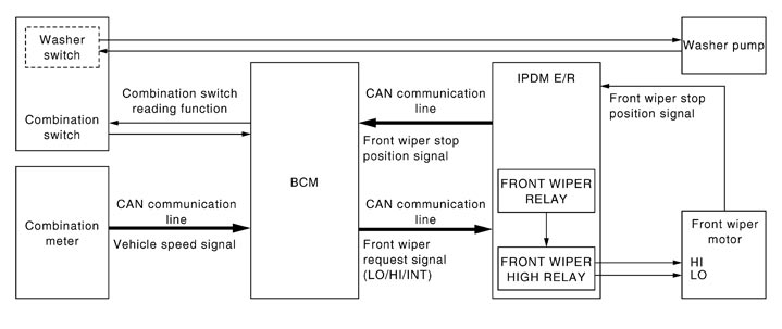
System Description
 OUTLINE
The front wiper is controlled by each function of BCM and IPDM E/R.
Control by BCM
- Combination switch reading function
- Front wiper control function
Control by IPDM E/R
- Front wiper control function
- Relay control function
FRONT WIPER BASIC OPERATION - BCM detects the combination switch condition by the combination switch reading function.
- BCM transmits the front wiper request signal to IPDM E/R with CAN communication depending on each operating condition of the front wiper.
- IPDM E/R turns ON/OFF the integrated front wiper relay and the front wiper high relay according to the front wiper request signal. IPDM E/R provides the power supply to operate the front wiper HI/LO operation.
FRONT WIPER LO OPERATION- BCM transmits the front wiper request signal (LO) to IPDM E/R with CAN communication according to the front wiper LO operating condition.
- Ignition switch ON
- Front wiper switch LO or front wiper switch MIST (while pressing)
- IPDM E/R turns ON the integrated front wiper relay according to the front wiper request signal (LO).
Front wiper LO operating condition
FRONT WIPER HI OPERATION- BCM transmits the front wiper request signal (HI) to IPDM E/R with CAN communication according to the front wiper HI operating condition.
- Ignition switch ON
- Front wiper switch HI
- IPDM E/R turns ON the integrated front wiper relay and the front wiper high relay according to the front wiper request signal (HI).
Front wiper HI operating condition
FRONT WIPER INT OPERATION- BCM transmits the front wiper request signal (INT) to IPDM E/R with CAN communication depending on the front wiper INT operating condition and intermittent operation delay interval according to the wiper intermittent dial position.
- Ignition switch ON
- Front wiper switch INT
- IPDM E/R turns ON the integrated front wiper relay so that the front wiper is operated only once according to the front wiper request signal (INT).
- BCM detects stop position/except stop position of the front wiper motor according to the front wiper stop position signal received from IPDM E/R with CAN communication.
- BCM transmits the front wiper request signal (INT) again after the intermittent operation delay interval.
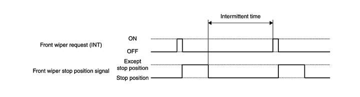
Front wiper INT operating condition
NOTE:
Factory setting of the front wiper intermittent operation is the operation without vehicle speed. Front wiper intermittent operation can be set to the operation with vehicle speed by CONSULT-III. Refer to CONSULT-III Function (BCM - WIPER).
 Front wiper intermittent operation
BCM determines intermittent operation delay interval according to a wiper volume.
| Wiper intermittent dial position | Intermittent operation interval | Intermittent operation delay Interval (s) |
| 1 | Short ↑ ↓ Long | 0.4 |
| 2 | 2 | |
| 3 | 5 | |
| 4 | 8 | |
| 5 | 12 | |
| 6 | 16 | |
| 7 | 21 |
FRONT WIPER AUTO STOP OPERATION- BCM stops transmitting the front wiper request signal when the front wiper switch is turned OFF.
- IPDM E/R detects the front wiper stop position signal from the front wiper motor and detects the front wiper motor position (stop position/except stop position).
- When the front wiper request signal is stopped, IPDM E/R turns ON the front wiper relay until the front wiper motor returns to the stop position.
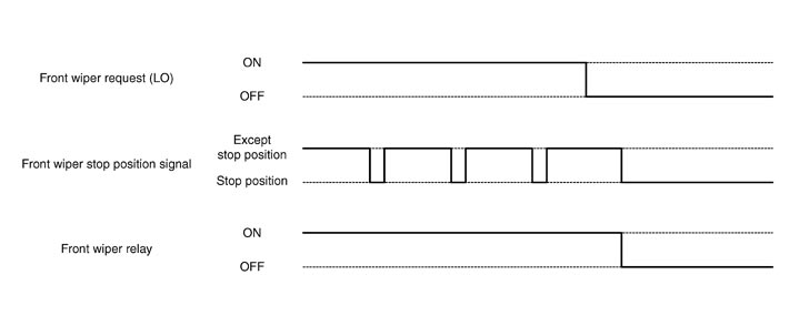
NOTE:
- BCM stops the transmitting of the front wiper request signal when the ignition switch OFF.
- IPDM E/R turns the front wiper relay OFF when the ignition switch OFF.
FRONT WIPER OPERATION LINKED WITH WASHER- BCM transmits the front wiper request signal (LO) to IPDM E/R with CAN communication according to the washer linked operating condition of the front wiper.
- BCM transmits the front wiper request signal (LO) so that the front wiper operates approximately 2 times when the front washer switch OFF is detected.
- Ignition switch ON
- Front washer switch ON (0.4 second or more)
- IPDM E/R turns ON the integrated front wiper relay according to the front wiper request signal (LO).
- The washer pump is grounded through the combination switch when the front washer switch ON.
Washer linked operating condition of front wiper
FRONT WIPER FAIL−SAFE OPERATIONWhen the front wiper auto stop circuit is malfunctioning, IPDM E/R performs the fail-safe function. Refer to Fail-safe.
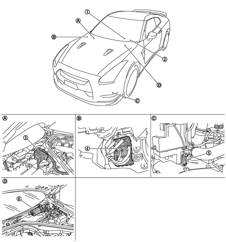
Component Parts Location
|
1. |
Combination switch |
2. |
Combination meter |
3. |
IPDM E/R |
|
4. |
BCM |
5. |
Washer pump |
6. |
Front wiper motor |
|
A. |
Engine room dash panel (RH) |
B. |
Dash side lower (Passenger side) |
C. |
Radiator core support (RH) |
|
D. |
Cowl top, left side of engine room |
|
|
|
|
Component Description
|
Part |
Description |
|
BCM |
|
|
IPDM E/R |
|
|
Combination switch (Wiper & washer switch) |
Refer to System Description. |
|
Combination meter |
Transmits the vehicle speed signal to BCM with CAN communication. |