FRONT WASHER NOZZLE AND TUBE
Hydraulic Layout
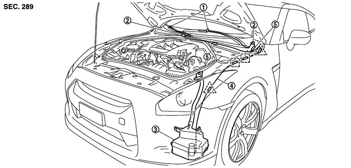
|
1. |
Front washer nozzle |
2. |
Front washer joint |
3. |
Washer tank |
|
4. |
Front washer tube |
5. |
Check valve |
|
|

|
Clip A |
|
|
|
|

|
Clip B |
|
|
|
|
Removal and Installation
 FRONT WASHER NOZZLE
The front washer nozzle must be replaced together with the front wiper arm as an assembly. Refer to Exploded View.
■ CAUTION ■
Never remove/install the front washer nozzle from the front wiper arm assembly. FRONT WASHER JOINT- 1.Remove upwards while pressing pawl (A) on reverse side.
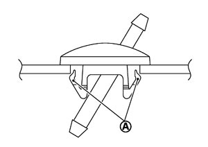
- 2.Disconnect front washer tube.
Inspection and Adjustment
INSPECTION Check valve Inspection
Check that air can pass through the hose by blowing forward (toward the nozzle), and check that air cannot pass through by sucking.
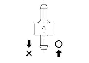 ADJUSTMENT Front Washer Nozzle Spray Position Adjustment
Adjust spray positions to match the positions shown in the figure. Remove the wiper motor connector to ensure front wiper arms do not move.
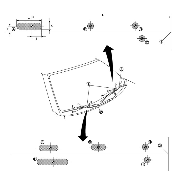
| 1. | Front washer nozzle | 2. | Passenger side blade rubber end | 3. | Driver side blade rubber end |
 | : Spray area | ||||
 | : Target spray position |
| Spray position | T | L | X | Y | S |
| A | 29 (1.14) | 448 (17.64) | 20 (0.79) | 50 (1.97) | 25 (0.98) |
| B | 34 (1.34) | 235 (9.25) | 20 (0.79) | 20 (0.79) | 10 (0.39) |
| C | −18 (−0.71) | 112 (4.41) | 20 (0.79) | 20 (0.79) | 10 (0.39) |
| D | 29 (1.14) | 115 (4.53) | 20 (0.79) | 20 (0.79) | 10 (0.39) |
| E | 30 (1.18) | 304 (11.97) | 20 (0.79) | 30 (1.18) | 15 (0.59) |
| F | −40 (−1.57) | 237 (9.33) | 20 (0.79) | 60 (2.36) | 30 (1.18) |
| G | 35 (1.38) | 197 (7.76) | 20 (0.79) | 30 (1.18) | 15 (0.59) |
| H | 30 (1.18) | 73 (2.87) | 20 (0.79) | 20 (0.79) | 10 (0.39) |
| I | −17 (−0.67) | 68 (2.68) | 20 (0.79) | 20 (0.79) | 10 (0.39) |
Insert a needle or similar object (A) into the spray opening (1) and move up/down and left/right to adjust the spray position.
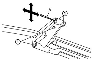
NOTE:
If wax or dust gets into the nozzle, remove wax or dust with a needle or small pin.