INSTRUMENT PANEL ASSEMBLY
Exploded View
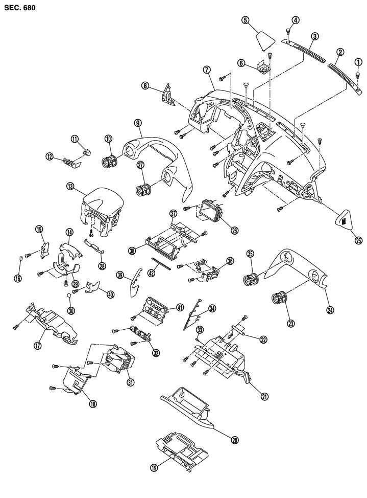
|
1. |
Sunload sensor |
2. |
Front defroster grille RH |
3. |
Front defroster grille LH |
|
4. |
Security indicator |
5. |
Center speaker grille |
6. |
Center speaker |
|
7. |
Instrument panel assembly |
8. |
Instrument side finisher LH |
9. |
Instrument pad A |
|
10. |
Side ventilator grille LH |
11. |
Mirror control switch |
12. |
Instrument pad B |
|
13. |
Cluster lid A |
14. |
Steering column upper cover |
15. |
Steering column side cover LH |
|
16. |
Steering column mask LH |
17. |
Instrument lower panel (driver) |
18. |
Cluster lid C (lower) |
|
19. |
Instrument lower cover LH |
20. |
Glove box assembly |
21. |
Instrument lower panel (assist) |
|
22. |
Globe box damper |
23. |
Side ventilator grille RH |
24. |
Instrument pad C |
|
25. |
Instrument side finisher RH |
26. |
Display unit |
27. |
Center ventilator grille LH |
|
28. |
Steering column front lower cover |
29. |
Steering column lower cover |
30. |
Steering column mask RH |
|
31. |
AV C/U |
32. |
Set-up switch assembly |
33. |
Socket & bulb |
|
34. |
Instrument garnish RH |
35. |
Center ventilator grille RH |
36. |
A/C auto amp. |
|
37. |
Multifunction switch |
38. |
Cluster lid C (upper) |
39. |
Instrument garnish LH |
|
40. |
Steering column side cover RH |
41. |
Preset switch assembly |
42. |
Instrument garnish (upper) |
Removal and Installation
 Work item table
|
PARTS |
INSTRUMENT PANEL ASSEMBLY |
COMBINATION METER |
DISPLAY UNIT |
AV control unit |
CENTER CONSOLE ASSEMBLY |
|
Rear console assembly |
[1] |
|
|
|
[1] |
|
Instrument garnish LH |
[2] |
|
[1] |
[1] |
[2] |
|
Instrument garnish RH |
[3] |
|
[2] |
[2] |
[3] |
|
Console finisher assembly |
[4] |
|
|
[3] |
[4] |
|
Instrument side panel LH |
[5] |
|
|
|
[5] |
|
Instrument side panel RH |
[6] |
|
|
|
[6] |
|
Center console assembly |
[7] |
|
|
|
[7] |
|
Control device assembly |
[8] |
|
|
|
|
|
Preset switch assembly |
[9] |
|
[3] |
[4] |
|
|
Set-up switch assembly |
[10] |
|
|
[5] |
|
|
Cluster lid C (lower) |
[11] |
|
|
[6] |
|
|
AV control unit |
[12] |
|
|
[7] |
|
|
A/C auto amp. |
[13] |
|
|
|
|
|
Instrument side finisher LH |
[14] |
|
|
|
|
|
Body side welt LH |
[15] |
|
|
|
|
|
Front pillar garnish LH |
[16] |
|
|
|
|
|
Instrument lower panel (driver) |
[17] |
|
|
|
|
|
Steering wheel |
[18] |
[1] |
[4] |
|
|
|
Steering column front lower cover |
[19] |
[2] |
[5] |
|
|
|
Steering column cover |
[20] |
[3] |
[6] |
|
|
|
Combination switch |
[21] |
[4] |
[7] |
|
|
|
Cluster lid A |
[22] |
[5] |
[8] |
|
|
|
Power socket |
[23] |
|
|
|
|
|
Instrument pad A |
[24] |
|
[9] |
|
|
|
Display unit |
[25] |
|
[10] |
|
|
|
Instrument pad B |
[26] |
|
|
|
|
|
Front defroster grille LH |
[27] |
|
|
|
|
|
Center speaker grille |
[28] |
|
|
|
|
|
Center speaker |
[29] |
|
|
|
|
|
Front defroster grille RH |
[30] |
|
|
|
|
|
Instrument side finisher RH |
[31] |
|
|
|
|
|
Body side welt RH |
[32] |
|
|
|
|
|
Front pillar garnish RH |
[33] |
|
|
|
|
|
Glove box lid |
[34] |
|
|
|
|
|
Instrument lower cover RH |
[35] |
|
|
|
|
|
Instrument lower panel (assist) |
[36] |
|
|
|
|
|
Instrument pad C |
[37] |
|
|
|
|
|
Instrument panel assembly |
[38] |
|
|
|
|
■ CAUTION ■
When removing, always use a remover tool that is made of plastic.
REMOVAL- 1.Remove the rear console assembly.
- Lift up the rear side of rear console assembly (1), and then disengage the pawls and the metal clips.
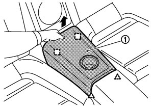
- Disconnect the harness connector on the back.

: Pawl 
: Metal clip
- 2.Remove the instrument garnish LH.
- Insert the remover tool (A), wrapped in a shop cloth, into the clearance between the lower side of instrument garnish LH (1) and the cluster lid C (lower) (2).
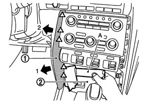
- Pull back the instrument garnish LH, and then disengage the pawls.
: Pawl
- 3.Remove the instrument garnish RH.
- Insert the remover tool (A), wrapped in a shop cloth, into the clearance between the lower side of instrument garnish RH (1) and the cluster lid C (lower) (2).
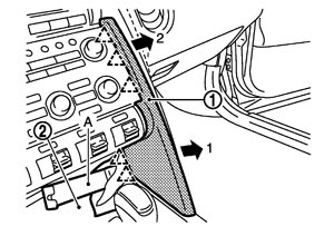
- Pull back the instrument garnish RH, and then disengage the pawls.
: Pawl
- 4.Remove the console finisher.
- Open the console lid.
- Insert the remover tool (A) between the console finisher (1) and the center console, lift up the console finisher, and then disengage the clips and the pawls.
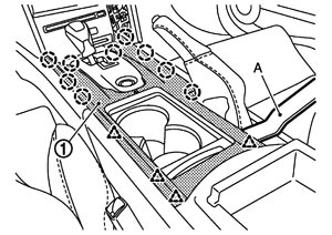

: Clip : Pawl
- 5.Remove the instrument side panel LH. Pull the instrument side panel LH (1) from vehicle front in lateral direction, then disengage the clips, pawl and the metal clips.
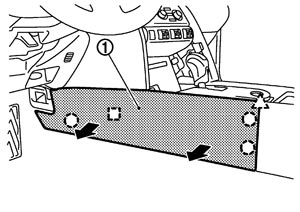
■ CAUTION ■
Be careful of the pawl when disengaging the clips. | : Clip |
| : Pawl |
| : Metal clip |
- 6.Remove the instrument side panel RH. Pull the instrument side panel RH (1) from vehicle front in lateral direction, then disengage the clips, pawl and the metal clips.
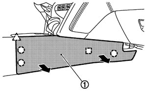
■ CAUTION ■
Be careful of the pawl when disengaging the clips. | : Clip |
| : Pawl |
| : Metal clip |
- 7.Remove the center console assembly.
- Remove the mounting screws (A) from front end of the center console (1).
- Remove the mounting nuts (B) from rear end of the center console.
- Lift up the center console, and then remove the harness clamps (C) and disconnect the harness connector from back side.
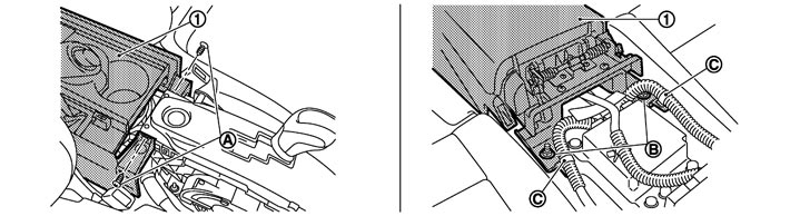
- 8.Remove the control device assembly. Refer to Removal and Installation.
- 9.Remove the preset switch assembly. Refer to Removal and Installation.
- Remove the instrument garnish (upper) using remover tool.
- Remove the mounting screw (A) of the preset switch assembly (1).
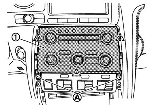
- Pull back the preset switch assembly, and then disengage the pawls.
- Disconnect the harness connectors on the back.
: Pawl
- 10.Remove the set-up switch assembly.
- Remove the mounting screws (A) of the set-up switch assembly (1).
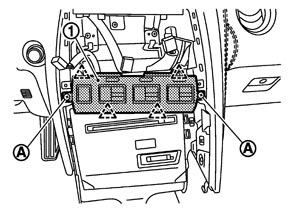
- Pull back the set-up switch assembly, and then disengage the pawls.
- Disconnect the harness connector on the back.
: Pawl
- 11.Remove the cluster lid C (lower).
- Remove the mounting screws (A) of the cluster lid C (lower) (1).
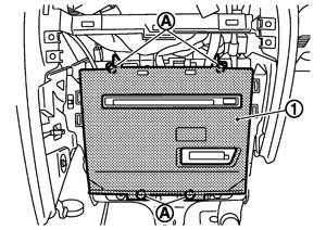
- Pull back the cluster lid C (lower).
- Disconnect the harness connector of back side and the harness connector of inside key antenna.
- 12.Remove the AV control unit. Refer to Removal and Installation.
- 13.Remove the A/C auto amp.
- Remove the mounting screws (A) of the A/C auto amp (1).
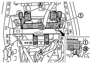
- Disengage the joint of harness clamp (B).
- Pull back the A/C auto amp.
- Disconnect the harness connectors on the back.
- 14.Remove the instrument side finisher LH.
- Insert the remover tool (A) between the instrument side finisher LH (1) and the instrument panel assembly.
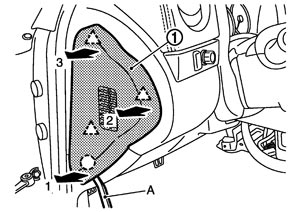
- Pull the instrument side finisher LH in lateral direction of the vehicle in order from 1 - 3, and then disengage the clip and the pawls.
: Clip : Pawl
- 15.Remove the body side welt LH. Refer to Removal and Installation.
- 16.Remove the front pillar garnish LH. Refer to Removal and Installation.
- 17.Disconnect the harness connectors (A) from the front pillar LH and remove the clips.
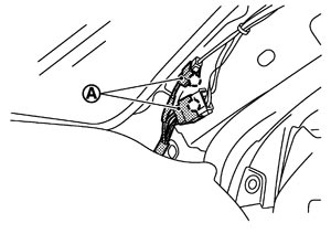
| : Clip |
- 18.Remove the instrument lower panel (driver).
- Remove the hood opener lever mounting bolts.
- Pull the instrument lower panel (driver) (1) toward vehicle lower, and then disengage the metal clips.
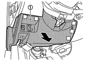
- Disconnect the harness connectors on the back.
: Metal clip
- 19.Remove the steering wheel. Refer to Removal and Installation.
- 20.Remove the steering column front lower cover. Pull down the steering column front lower cover (1) toward vehicle lower, and then disengage the clips.
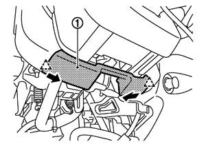
| : Pawl |
NOTE:
Move the steering column position frontward using the telescopic function. - 21.Remove the steering column cover.
- Remove the steering column mask LH/RH (1), and then remove the screws (A).
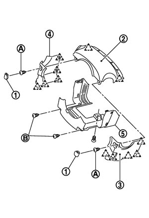
- Pull up the steering column upper cover (2), and then disengage the pawls.
- Disengage the pawls of the steering column side cover RH (3), and then remove it in the lateral direction of the vehicle.
- Disengage the pawls of the steering column side cover LH (4), and then remove it in the lateral direction of the vehicle.
- Remove the mounting screws (B), and then remove the steering column lower cover (5).
: Pawl
- 22.Remove the spiral cable. Refer to Removal and Installation.
- 23.Remove the combination switch. Refer to Removal and Installation.
- 24.Remove the cluster lid A.
- Remove the mounting bolts (A) from lower side of the cluster lid A (1).
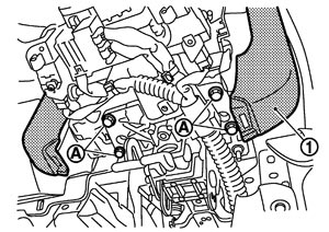
- Pull the cluster lid A toward vehicle upper.
- Disconnect the harness connector on the back.
- 25.Remove the power socket. Refer to Removal and Installation.
- 26.Remove the instrument pad A.
- Lift up the portion around the side ventilator grille LH, and then disengage the pawls and the metal clips.
- Lift up the portion around the center ventilator grille LH, and then disengage the pawls and the metal clips.
- Lift up the portion around the display unit RH, and then disengage the pawls and the metal clips.
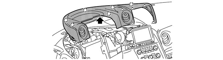
| : Pawl |
| : Metal clip |
- 27.Remove the display unit. Refer to Removal and Installation.
- 28.Remove the remote keyless entry receiver. Refer to Removal and Installation.
- 29.Remove instrument pad B.
- Pull back the instrument pad B (1), and then disengage the clips.
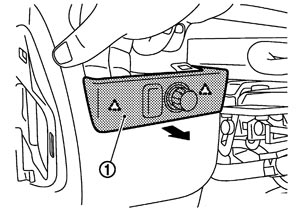
- Disconnect the harness connector on the back.
| : Pawl |
- 30.Remove the front defroster grille LH. Refer to Removal and Installation.
- 31.Remove the center speaker grille.
- Insert the remover tool (A) between the center speaker grille (1) and the instrument panel assembly (2), and then disengage the clips and pawls.
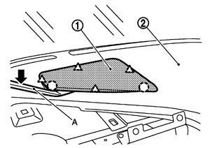
- Lift upward.
: Clip : Pawl
- 32.Remove the center speaker. Refer to Exploded View.
- 33.Remove the front defroster grille RH. Refer to Removal and Installation.
- 34.Remove the instrument side finisher RH.
- Insert the remover tool (A) between the instrument side finisher RH (1) and the instrument panel assembly.
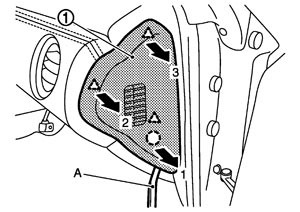
- Pull the instrument side finisher RH in lateral direction in order of 1 - 3, and then disengage the clip and the pawls.
: Clip : Pawl
- 35.Remove the body side welt RH. Refer to Removal and Installation.
- 36.Remove the front pillar garnish RH. Refer to Removal and Installation.
- 37.Remove glove box assembly.
- Open the glove box.
- Pull the glove box assembly (1) toward vehicle upper, and then disengage the joint from the instrument lower panel RH.
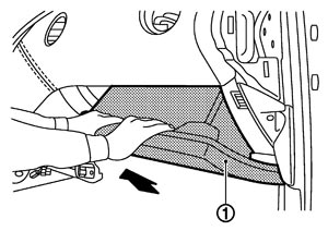
- Remove the damper pin (2) from the glove box assembly (1).
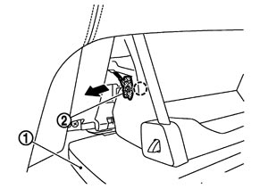
: Clip
- 38.Remove the instrument lower cover RH.
- Insert the remover tool (A) between the instrument lower cover RH (1) and the instrument panel assembly (2), and then disengage the pawls.
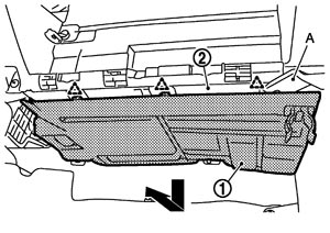
- Pull out the instrument lower cover RH toward vehicle lower, then back.
: Pawl
- 39.Remove the instrument lower panel (assist).
- Remove the mounting screws (A).
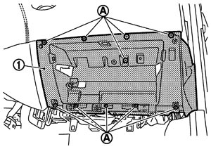
- Pull back out the instrument lower panel (assist) (1).
- Disconnect the harness connector of back side and remove the harness clamp.
- 40.Remove instrument pad C. Pull the instrument pad C (1) in order from 1 - 3, and then disengage the metal clips.
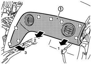
| : Metal clip |
- 41.Disconnect the harness connector of front passenger air bag module. Refer to Exploded View.
- 42.Remove the front passenger air bag module mounting bolt. Refer to Removal and Installation.
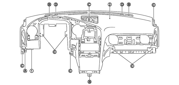
- 43.Remove the instrument panel assembly.
- Remove the mounting bolt (A) of the instrument side bracket (1).
- Remove the mounting bolt (B) of the instrument panel assembly (2).
- Remove the mounting screw (C) of the instrument panel assembly.
- Remove the front defroster nozzle mounting clip (D).
- Pull out the instrument panel assembly toward the rear of the vehicle, and then remove it from the door opening. ■ CAUTION ■When removing instrument panel assembly, 2 workers are required to prevent it from dropping.
- 44.Remove the following parts after removing the instrument panel assembly.
- Front passenger air bag module: Refer to Removal and Installation.
- GPS antenna: Refer to Removal and Installation.
- Antenna feeder: Refer to Harness layout.
- Monitor bracket
INSTALLATIONInstall in the reverse order of removal.