RADIATOR CORE SUPPORT
Exploded View
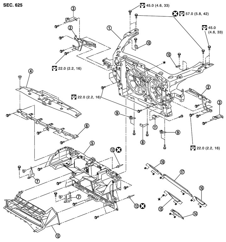
|
1. |
Radiator core support assembly |
2. |
Hood lock bracket assembly (LH/RH) |
3. |
Bumper clip bracket (LH/RH) |
|
4. |
Radiator cover |
5. |
Air intake duct assembly 1 |
6. |
Bumper fascia bracket |
|
7. |
Air guide bracket (LH/RH) |
8. |
Air duct bracket lower |
9. |
Radiator under bracket (LH/RH) |
|
10. |
Air cleaner bracket (LH/RH) |
11. |
Power steering pipe bracket |
12. |
Rivet |
|
13. |
Air intake duct assembly 2 |
14. |
Flap (lower) |
15. |
Flap (center) |
|
16. |
Flap (LH) |
17. |
Flap (upper) |
18. |
Flap (RH) |
|
Refer to Components for the symbol shown in the figure. |
|||||
Removal and Installation
 REMOVAL
- 1.Discharge refrigerant. Refer to Collection and Charge.
- 2.Disengage the clips, and then remove the radiator cover.
- 3.Remove the front bumper fascia and the bumper reinforcement. Refer to Removal and Installation.
- 4.Remove the dust duct side (LH/RH). Refer to Exploded View.
- 5.Remove the harness clip and hood lock cable clamp from the bumper fascia bracket.
- 6.Remove the hood lock cable clamp from the air intake duct assembly 1.
- 7.Disengage the connector of horns (HIGH/LOW). Refer to Removal and Installation.
- 8.Disengage the hood lock switch connector of hood lock (LH).
- 9.Disconnect the ambient sensor connector. Refer to Removal and Installation.
- 10.Remove the power steering oil cooler mounting bolt. Refer to Exploded View.
- 11.Remove the washer tank and the washer tank inlet. Refer to Exploded View.
- 12.Disconnect the air inlet hose, air inlet pipe, and recirculation hose from the charge air cooler assembly (bank 1 and bank 2). Refer to Exploded View.
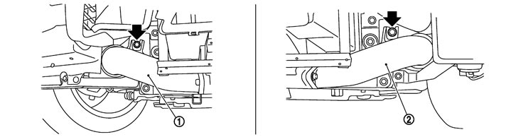
- 13.Remove the mounting bolts (arrows shown in the figure) of charge air cooler assembly [bank 1: (1), bank 2: (2)] as shown in the figure.
- 14.Remove the mounting bolts of the hood lock (LH/RH).
- 15.Check that all connections of connector, hose, and pipe are disconnected from the air intake duct assembly.
- 16.Remove the mounting bolts, and then remove the air intake duct assembly.
- 17.Remove the hood lock (LH/RH) from the air intake duct assembly 1. Refer to Removal and Installation (GT-R certified NISSAN dealer).
- 18.Disconnect the refrigerant pressure sensor connector. Refer to Exploded View (GT-R certified NISSAN dealer).
- 19.Remove the front combination lamp assembly (LH/RH). Refer to Removal and Installation.
- 20.Remove the air inlet hose and the air inlet pipe assembly connected to the upper side of charge air cooler (bank 1 and bank 2). Refer to Exploded View.
- 21.Remove the power steering oil cooler. Refer to Exploded View.
- 22.Remove the engine oil cooler. Refer to Removal and Installation (GT-R certified NISSAN dealer).
- 23.Remove the air cleaner. Refer to Exploded View.
- 24.Disconnect the high-pressure flexible hose and high-pressure pipe 1 from the condenser. Refer to Removal and Installation (GT-R certified NISSAN dealer) and Removal and Installation (GT-R certified NISSAN dealer).
- 25.Drain the coolant from the radiator. Refer to Draining.
- 26.Remove the coolant reservoir tank. Refer to Exploded View (GT-R certified NISSAN dealer).
- 27.Remove the front side mounting bolt of engine undercover. Refer to Removal and Installation.
- 28.Remove the power steering fluid reservoir tank. Refer to Exploded View.
- 29.Disengage the joint of power steering fluid pipe and radiator core support assembly at the radiator core support side.
- 30.Disconnect the cooling fan connector.
- 31.Disconnect the crash zone sensor connector.
- 32.Remove the mounting bolts, and then remove the hood lock bracket (LH/RH).
- 33.Remove the radiator & condenser assembly. Refer to Removal and Installation (GT-R certified NISSAN dealer).
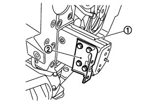
- 34.Remove the mounting bolt, and then remove the stay (LH/RH) (2) that is next to the side member (1).
- 35.Disconnect all harness clamp from the radiator core support assembly.
- 36.Check that all connections of connector, hose, and pipe are disconnected from the radiator core support assembly.
- 37.Remove the mounting bolt, and then remove the radiator core support assembly.
INSTALLATIONInstall in the reverse order of removal.
■ CAUTION ■
- Never reuse the bolt connecting the front strut housing with the radiator core support. Use a genuine part.
- Tighten to the specified torque.
- Refill the following parts after installation.
- Refrigerant: Refer to Collection and Charge.
- Power steering fluid: Refer to Inspection.
- Engine oil: Refer to Refilling.
- Engine coolant: Refer to Refilling.
- Perform aiming adjustment of front combination lamp after installation. Refer to Aiming Adjustment Procedure.
Disassembly and assembly
RADIATOR CORE SUPPORT ASSEMBLY Disassembly
- 1.Remove the crash zone sensor. Refer to Removal and Installation.
- 2.Remove the cooling fan (LH/RH), cooling fan control module, fan motor, and fan motor cover. Refer to Removal and Installation (GT-R certified NISSAN dealer).
- 3.Remove all flaps.
AssemblyAssemble in the reverse order of disassembly.
AIR INTAKE DUCT ASSEMBLY Disassembly- 1.Remove the rivets, and then remove the air intake duct assembly 2.
- Grind the head of rivet (1) with a drill (A) (blade of φ4.0 - 4.5 mm), and then remove the air intake duct 2.
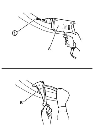
- Securely crimp it with the air intake duct 2 using a hand riveter (B).
NOTE:
Removal and installation of rivet| Air intake duct | |
| Crimping thickness | : 0.5 – 6.4 mm (0.020 – 0.252 in) |
| Prepared hole diameter | : φ 5.1 |
- 2.Remove the charge air cooler. Refer to Removal and Installation.
- 3.Remove the mounting bolts, and then remove the bumper fascia bracket.
- 4.Remove the horn (HIGH/LOW). Refer to Removal and Installation.
- 5.Remove the ambient sensor. Refer to Removal and Installation.
- 6.Remove the clips and mounting bolts, and then remove the air guide bracket.
AssemblyAssemble in the reverse order of disassembly.