DOOR ASSEMBLY
DOOR
Exploded View
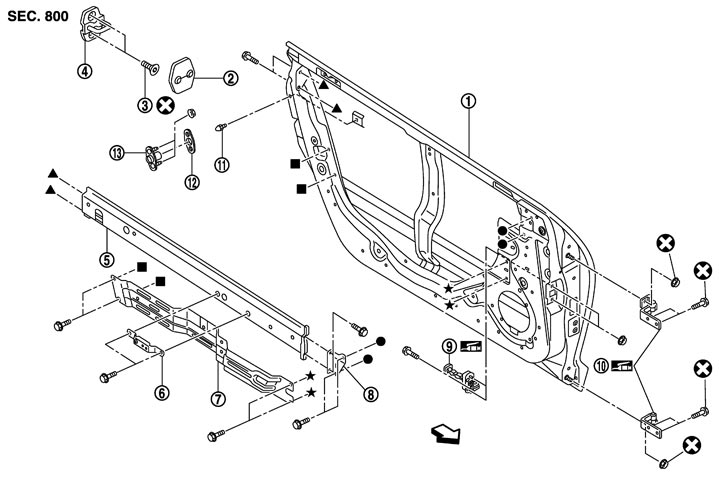
|
1. |
Door panel |
2. |
Door striker cover |
3. |
TORX bolt |
|
4. |
Door striker |
5. |
Door inner west reinforcement |
6. |
Door grip bracket |
|
7. |
Door module assembly |
8. |
Bracket |
9. |
Check link |
|
10. |
Door hinge |
11. |
Dovetail male |
12. |
Dovetail female cover |
|
13. |
Dovetail female |
|
|
|
|
 : Vehicle front : Vehicle front |
|||||
|
Refer to Components for the symbols shown in the figure. |
|||||
Removal and Installation
■ CAUTION ■
- Operate with two workers, because of its heavy weight.
- Support door with a jack and use protective tape or shop cloth to protect from damage during removal and installation.
 REMOVAL
- 1.Disconnect the door harness connector.
- 2.Remove the door check link mounting bolts (body side).
- 3.Remove the door hinge mounting nuts (door side), and then remove the door assembly.
INSTALLATIONInstall in the reverse order of removal.
■ CAUTION ■
- Never reuse bolts and nuts connecting the door hinge with the door striker. Use the specified bolts and nuts when installing.
- Apply anticorrosive agent onto the mounting surface.
- After installation, perform the fitting adjustment. Refer to Adjustment.
- After installation, apply touch-up paint (the body color) onto the head of door hinge mounting bolts and nuts.
Adjustment
ADJUSTMENT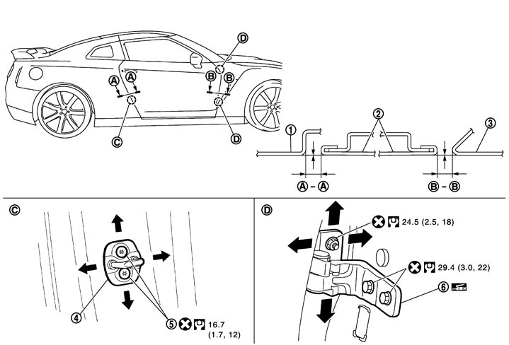
|
1. |
Rear fender |
2. |
Door panel |
3. |
Front fender |
|
4. |
Door striker |
5. |
TORX bolt |
6. |
Door hinge |
|
Refer to Components for the symbols shown in the figure. |
|||||
Check both visually and by touch that the clearance and surface height difference of the door panel and each part are within the specified value. If they are out of the specified value, adjust them as per the following procedures.
| Location | Standard | ||
| Rear fender and door panel | A – A | Clearance | 3.0 – 5.0 (0.118 – 0.197) |
| Surface height | -1.0 – 1.0 (-0.039 – 0.039) | ||
| Door panel and front fender | B – B | Clearance | 3.0 – 5.0 (0.118 – 0.197)) |
| Surface height | -1.0 – 1.0 (-0.039 – 0.039) | ||
- 1.Remove the front fender. Refer to Removal and Installation.
- 2.Loosen the door hinge mounting bolts (door side).
- 3.Adjust the surface height difference within the specified value as shown in the table, while moving the door.
- 4.Tighten the door hinge mounting bolts (door side).
- 5.Loosen the door hinge mounting bolts (body side).
- 6.Adjust the clearance within the specified value as shown in the table, while moving the door rear end up or down.
- 7.Tighten the door hinge mounting nuts and bolts to the specified torque after adjustment.
- Apply anticorrosive agent onto the mounting surface.
- Check door hinge rotating part for poor lubrication. If necessary, apply body grease.
- After installation, check door open/close, lock/unlock operation.
■ CAUTION ■
- 8.Install the front fender. Refer to Removal and Installation.
■ CAUTION ■
After installation, apply touch-up paint (the body color) onto the head of door hinge mounting bolts and nuts. STRIKER ADJUSTMENTAdjust the striker until it is parallel to the lock engagement direction.