COMPRESSOR CONTROL FUNCTION
AUTOMATIC AIR CONDITIONER
Description
 OPERATION PRINCIPLE
 Functional Circuit Diagram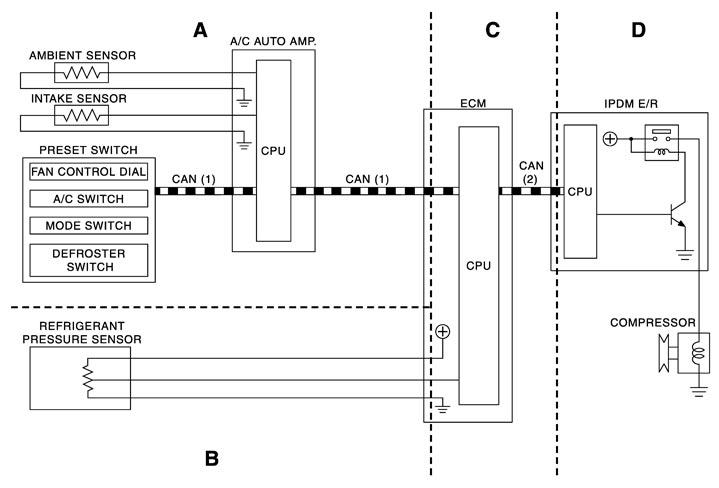
|
CAN (1) |
: A/C switch signal : Blower fan motor switch signal |
CAN (2) |
: A/C compressor request signal |
Functional Initial Inspection Chart|
Control unit |
Diagnosis item |
Location |
||||
|
A |
B |
C |
D |
|||
|
A/C auto amp. |
 “HVAC” “HVAC” |
Self-diagnosis |
× |
‐ |
‐ |
‐ |
|
Data monitor |
× |
‐ |
‐ |
‐ |
||
|
Active test |
× |
‐ |
‐ |
× |
||
|
ECM |
“ENGINE” |
Self-diagnosis function (CAN system diagnosis) |
‐ |
‐ |
× |
‐ |
|
Data monitor |
‐ |
× |
× |
‐ |
||
|
IPDM E/R |
“IPDM E/R” |
Self-diagnosis function (CAN system diagnosis) |
‐ |
‐ |
‐ |
× |
|
Data monitor |
‐ |
‐ |
× |
|
||
|
Auto active test |
‐ |
‐ |
‐ |
× |
||
Fail-safe
FAIL-SAFE FUNCTIONWhen a communication malfunction between A/C auto amp., and AV control unit and preset switch continued for approximately 30 seconds or more, control the air conditioner under the following conditions.
| Compressor | : ON |
| Air outlet | : AUTO |
| Air inlet | : FRE (Fresh air intake) |
| Blower speed | : AUTO |
| Preset temperature | : Setting before communication error occurs |
| A/C display | : OFF |
Component Parts Location
ENGINE COMPARTMENT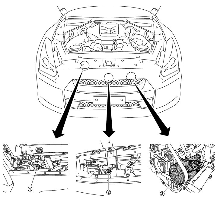
|
1. |
Refrigerant pressure sensor |
2. |
Ambient sensor |
3. |
Compressor (magnetic clutch) |
PASSENGER COMPARTMENT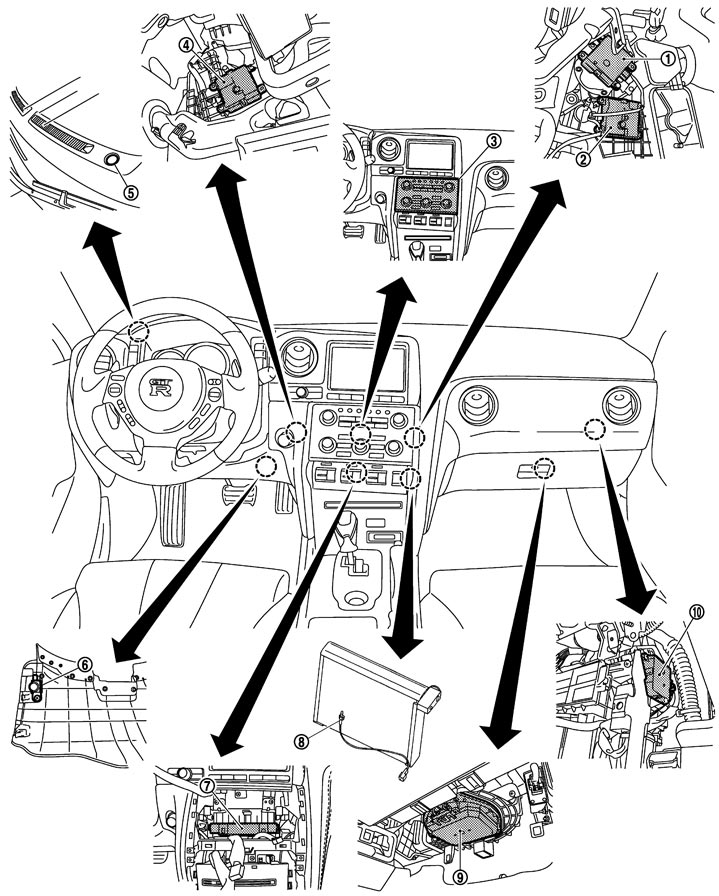
|
1. |
Mode door motor |
2. |
Air mix door motor (passenger side) |
3. |
Preset switch |
|
4 |
Air mix door motor (driver side) |
5. |
Sunload sensor |
6. |
In-vehicle sensor |
|
7. |
A/C auto amp. |
8. |
Intake sensor |
9. |
Blower motor |
|
10. |
Intake door motor |
|
|
|
|
Component Description
|
Component |
Reference |
|
Air mix door motor (driver side) |
Description
|
|
Air mix door motor (passenger side) |
Description
|
|
Ambient sensor |
Description
|
|
A/C auto amp. |
Description
|
|
Blower motor |
Description
|
|
Compressor |
Description
|
|
Intake door motor |
Description
|
|
Intake sensor |
Description
|
|
In-vehicle sensor |
Description
|
|
Mode door motor |
Description
|
|
Preset switch |
The preset switch integrated with the controller for A/C operation and AV switch is installed to the center of the instrument panel. The operation and display data of the preset switch are communicated with the A/C auto amp. through AV control unit via CAN communication. |
|
Refrigerant pressure sensor |
Description (GT-R certified NISSAN dealer)
|
|
Sunload sensor |
Description
|