A/C AUTO AMP.
AUTOMATIC AIR CONDITIONER
- Reference Value
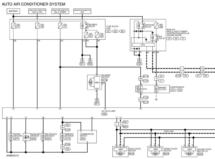
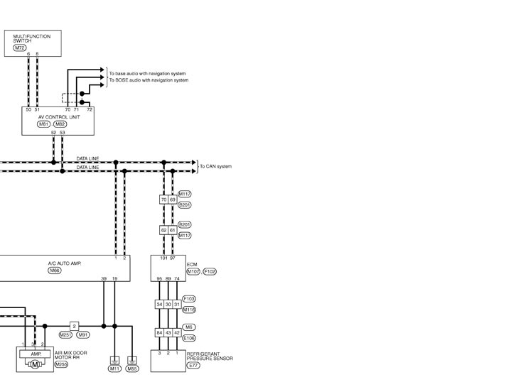
- Wiring Diagram - AIR CONDITIONER CONTROL SYSTEM -
- Fail-safe
- DTC Inspection Priority Chart
- DTC Index
Reference Value
 CONSULT‐III DATA MONITOR REFERENCE VALUES
|
Monitor item |
Condition |
Value/Status | |
| COMP REQ SIG | Engine: Run at idle after warming up | A/C switch: ON (Compressor operation status) | On |
| A/C switch: OFF | Off | ||
| FAN REQ SIG | Engine: Run at idle after warming up | Blower motor: ON | On |
| Blower motor: OFF | Off | ||
| AMB TEMP SEN | Ignition switch ON | — | −22 – 131°F (−30 – 55°C) |
| IN‐VEH TEMP | Ignition switch ON | — | −22 – 131°F (−30 – 55°C) |
| INT TEMP SEN | Ignition switch ON | — | −22 – 131°F (−30 – 55°C) |
| SUNLOAD SEN | Ignition switch ON | — | 0 – 1045 w/m2 (0 – 900 kcal/m2·h) |
| AMB SEN CAL | Ignition switch ON | — | −22 – 131°F (−30 – 55°C) |
| IN‐VEH CAL | Ignition switch ON | — | −22 – 131°F (−30 – 55°C) |
| INT TEMP CAL | Ignition switch ON | — | −22 – 131°F (−30 – 55°C) |
| SUNL SEN CAL | Ignition switch ON | — | 0 – 1045 w/m2 (0 – 900 kcal/m2·h) |
| FAN DUTY | Engine: Run at idle after warming up | Blower motor: ON | 25 – 81% |
| Blower motor: OFF | 0% | ||
| XM | Ignition switch ON | — | −100 – 155 |
| ENG COOL TEMP | Ignition switch ON | — | Values according to coolant temperature |
| VEHICLE SPEED | Driving | — | Equivalent to speedometer reading |
TERMINAL LAYOUT PHYSICAL VALUES
|
Terminal No. (Wire color) |
Description |
Condition |
Value (Approx.) |
|||
|
+ |
− |
Signal name |
Input/Output |
|||
|
1 (L) |
Ground |
CAN - H |
Input/Output |
— |
— |
|
|
2 (P) |
Ground |
CAN - L |
Input/Output |
— |
— |
|
|
10 (L) |
Ground |
A/C LAN signal |
Input/Output |
Ignition switch ON |
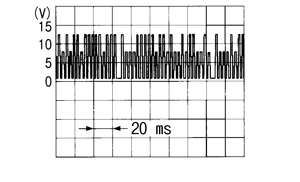
|
|
|
11 (R) |
Ground |
Each door motor power supply |
— |
Ignition switch ON |
12 V |
|
|
15 (O) |
Ground |
Sunload sensor signal |
Input |
— |
0 – 4.8 V Output voltage varies with sunload amount |
|
|
16 (R) |
Ground |
Intake sensor signal |
Input |
— |
0 – 4.8 V Output voltage varies with intake temperature |
|
|
17 (V) |
Ground |
ACC power supply |
— |
Ignition switch ACC |
Battery voltage |
|
|
19 (B) |
Ground |
Ground |
— |
Ignition switch ON |
0 V |
|
|
20 (G) |
Ground |
Ignition power supply |
— |
Ignition switch ON |
Battery voltage |
|
|
24 (O) |
Ground |
ECV (Electric Control Value) signal |
Output |
|
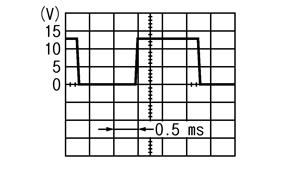
|
|
|
32 (L) |
Ground |
Blower motor control signal |
Output |
|
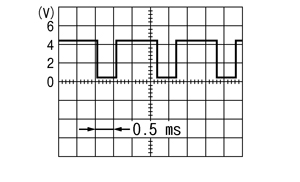
|
|
|
34 (Y) |
Ground |
A/C auto amp. connecting recognition signal |
Output |
Ignition switch ON |
5 V |
|
|
35 (P) |
Ground |
Ambient sensor signal |
Input |
— |
0 – 4.8 V Output voltage varies with ambient temperature |
|
|
36 (LG) |
Ground |
In-vehicle sensor signal |
Input |
— |
0 – 4.8 V Output voltage varies with in-vehicle temperature |
|
|
37 (O) |
Ground |
Sensor ground |
— |
Ignition switch ON |
0 V |
|
|
39 (B) |
Ground |
Ground |
— |
Ignition switch ON |
0 V |
|
|
40 (Y) |
Ground |
Battery power supply |
— |
Ignition switch OFF |
Battery voltage |
|
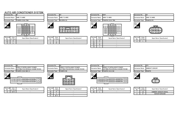
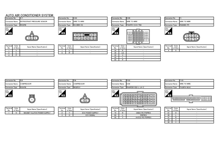
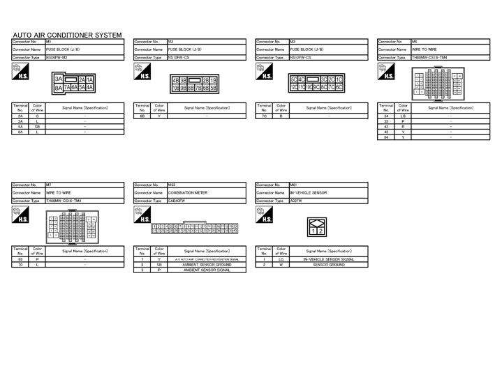
Wiring Diagram - AIR CONDITIONER CONTROL SYSTEM -
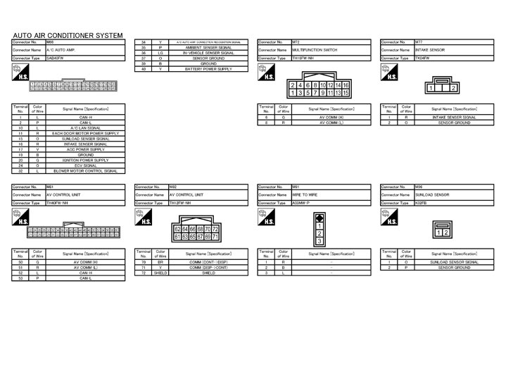
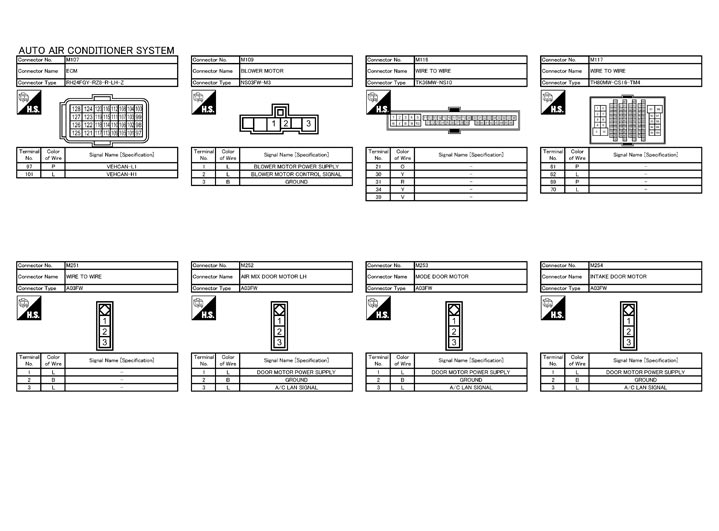
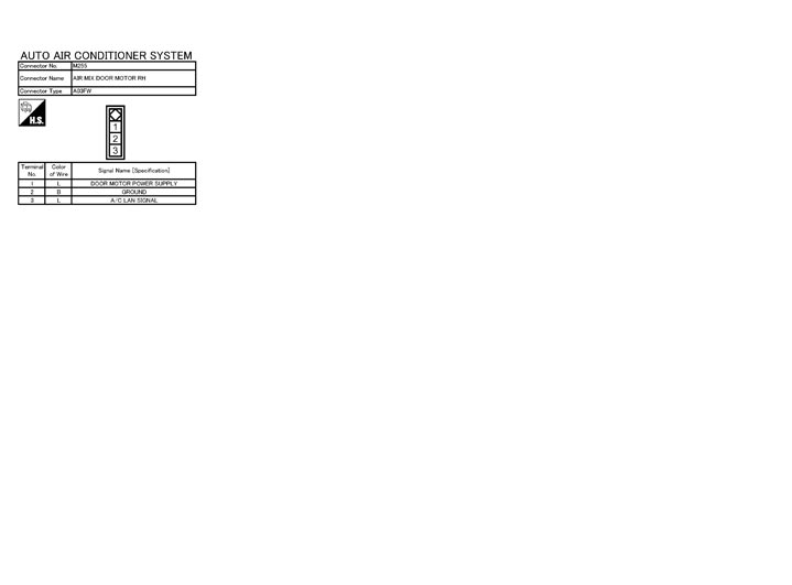
Fail-safe
FAIL-SAFE FUNCTIONWhen a communication malfunction between A/C auto amp. and AV control unit and preset switch continued for approximately 30 seconds or more, control the air conditioner under the following conditions.
| Compressor | : ON |
| Air outlet | : AUTO |
| Air inlet | : FRE (Fresh air intake) |
| Blower speed | : AUTO |
| Preset temperature | : Setting before communication malfunction |
| A/C display | : OFF |
DTC Inspection Priority Chart
If some DTCs are displayed at the same time, perform inspections one by one based on the following priority chart.
| Priority | Detected items (DTC) |
| 1 |
|
| 2 |
|
DTC Index
|
DTC |
Items (CONSULT‐III screen terms) |
Reference |
|
U1000 |
CAN COMM CIRCUIT |
DTC Logic
|
|
U1010 |
CONTROL UNIT (CAN) |
DTC Logic
|
|
B257B |
AMB TEMP SEN (SHORT) |
DTC Logic
|
|
B257C |
AMB TEMP SEN (OPEN) |
DTC Logic
|
|
B2578 |
IN CAR SENSOR (OUT OF RANGE [LOW]) |
DTC Logic
|
|
B2579 |
IN CAR SENSOR (OUT OF RANGE [HI]) |
DTC Logic
|
|
B2581 |
EVAP TEMP SEN (SHORT) |
DTC Logic
|
|
B2582 |
EVAP TEMP SEN (OPEN) |
DTC Logic
|
|
B2630* |
SUNLOAD SEN (SHORT) |
DTC Logic
|
|
B2631* |
SUNLOAD SEN (OPEN) |
DTC Logic
|
|
B2632 |
DR AIRMIX ACTR (SHORT) |
DTC Logic
|
|
B2633 |
DR AIRMIX ACTR (OPEN) |
DTC Logic
|
|
B2634 |
PASS AIRMIX ACTR (SHORT) |
DTC Logic
|
|
B2635 |
PASS AIRMIX ACTR (OPEN) |
DTC Logic
|
|
B2636 |
DR VENT DOOR FAIL |
DTC Logic
|
|
B2637 |
DR B/L DOOR FAIL |
DTC Logic
|
|
B2638 |
DR D/F1 DOOR FAIL |
DTC Logic
|
|
B2639 |
DR DEF DOOR FAIL |
DTC Logic
|
|
B263D |
FRE DOOR FAIL |
DTC Logic
|
|
B263E |
20P FRE DOOR FAIL |
DTC Logic
|
|
B263F |
REC DOOR FAIL |
DTC Logic
|
|
B2654 |
D/F2 DOOR FAIL |
DTC Logic
|
|
B2655 |
B/L2 DOOR FAIL |
DTC Logic
|
|
B2656 |
BTC FRE DOOR FAIL |
DTC Logic
|