POWER CONTROL SYSTEM
IPDM E/R
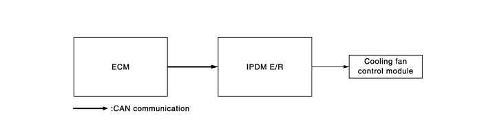
System Diagram
System Description
 COOLING FAN CONTROL
IPDM E/R outputs pulse duty signal (PWM signal) to the cooling fan control module according to the status of the cooling fan speed request signal received from ECM via CAN communication. Refer to System Diagram (GT-R certified NISSAN dealer).
NOTE:
After ignition switch OFF, IPDM E/R turn the cooling fan relay ON and outputs pulse duty signal (PWM signal) to the cooling fan control module according to the request signal from ECM for cooling an engine by the situation. Refer to Engine Cooling System (GT-R certified NISSAN dealer).
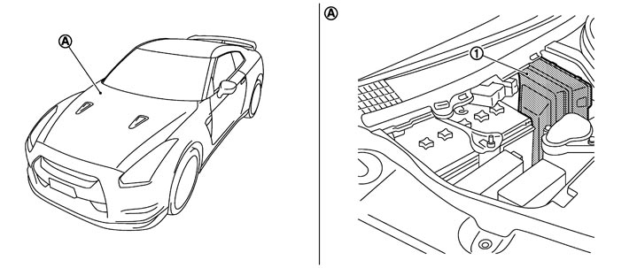
Component Parts Location
|
1. |
IPDM E/R |
|
|
|
|
|
A. |
Engine room dash panel (RH) |
|
|
|
|