IPDM E/R (INTELLIGENT POWER DISTRIBUTION MODULE ENGINE ROOM)
IPDM E/R
Reference Value
 VALUES ON THE DIAGNOSIS TOOL
|
Monitor Item |
Condition |
Value/Status | |
| RAD FAN REQ | Engine idle speed | Changes depending on engine coolant temperature, air conditioner operation status, vehicle speed, etc. | 0 ‐ 100 % |
| AC COMP REQ | Engine running | A/C switch OFF | Off |
| A/C switch ON (Compressor is operating) | On | ||
| TAIL&CLR REQ | Lighting switch OFF | Off | |
| Lighting switch 1ST, 2ND or HI | On | ||
| HL LO REQ | Lighting switch OFF | Off | |
| Lighting switch 2ND or HI | On | ||
| HL HI REQ | Lighting switch OFF | Off | |
| Lighting switch HI | On | ||
| FR FOG REQ | NOTE: The item is indicated, but not monitored. | Off | |
| FR WIP REQ | Ignition switch ON | Front wiper switch OFF | Stop |
| Front wiper switch INT | 1LOW | ||
| Front wiper switch LO | Low | ||
| Front wiper switch HI | Hi | ||
| WIP AUTO STOP | Ignition switch ON | Front wiper stop position | STOP P |
| Any position other than front wiper stop position | ACT P | ||
| WIP PROT | Ignition switch ON | Front wiper operates normally | Off |
| Front wiper stops at fail-safe operation | BLOCK | ||
| IGN RLY1 ‐REQ | Ignition switch OFF or ACC | Off | |
| Ignition switch ON | On | ||
| IGN RLY | Ignition switch OFF or ACC | Off | |
| Ignition switch ON | On | ||
| PUSH SW | Release the push‐button ignition switch | Off | |
| Press the push‐button ignition switch | On | ||
| INTER/NP SW | Ignition switch ON | Shift lever in any position other than P or N | Off |
| Ignition switch ON | Shift lever in P or N position | On | |
| ST RLY CONT | Ignition switch ON | Off | |
| At engine cranking | On | ||
| IHBT RLY ‐REQ | Ignition switch ON | Off | |
| At engine cranking | On | ||
| ST/INHI RLY | Ignition switch ON | Off | |
| At engine cranking | INHI → ST | ||
| The status of starter relay or starter control relay cannot be recognized by the battery voltage malfunction, etc. when the starter relay is ON and the starter control relay is OFF | UNKWN | ||
| DETENT SW | Ignition switch ON |
| Off |
| Release the knob button with shift lever in P position | On | ||
| S/L RLY ‐REQ | None of the conditions below are present | Off | |
| On | ||
| S/L STATE | Steering lock is activated | LOCK | |
| Steering lock is deactivated | UNLOCK | ||
| [DTC: B210A] is detected | UNKWN | ||
| DTRL REQ NOTE: This item is monitored only on the vehicle with the daytime running light system. | Daytime running light system is not operated | Off | |
| Daytime running light system is operated | On | ||
| OIL P SW | NOTE: The item is indicated, but not monitored. | Open | |
| HOOD SW | Close the hood | Off | |
| Open the hood | On | ||
| HL WASHER REQ | NOTE: The item is indicated, but not monitored. | Off | |
| THFT HRN REQ | Not operating | Off | |
| On | ||
| HORN CHIRP | Not operating | Off | |
| On | ||
| CRNRNG LMP REQ | NOTE: The item is indicated, but not monitored. | Off | |
TERMINAL LAYOUT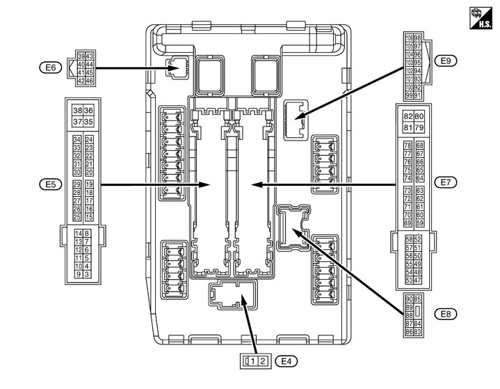 PHYSICAL VALUES
|
Terminal No. (Wire color) |
Description |
Condition |
Value (Approx.) |
|||
|
Signal name |
Input/ Output |
|||||
|
+ |
− |
|||||
|
1 (W) |
Ground |
Battery power supply |
Input |
Ignition switch OFF |
Battery voltage |
|
|
2 (Y) |
Ground |
Battery power supply |
Input |
Ignition switch OFF |
Battery voltage |
|
|
4 (V) |
Ground |
Front wiper LO |
Output |
Ignition switch ON |
Front wiper switch OFF |
0 V |
|
Front wiper switch LO |
Battery voltage |
|||||
|
5 (L) |
Ground |
Front wiper HI |
Output |
Ignition switch ON |
Front wiper switch OFF |
0 V |
|
Front wiper switch HI |
Battery voltage |
|||||
|
6* (O) |
Ground |
Daytime running light relay power supply |
Input |
Ignition switch OFF |
Battery voltage |
|
|
Daytime running light system operated |
0 V |
|||||
|
7 (R) |
Ground |
Tail, rear side marker, license plate lamps & illuminations |
Output |
Ignition switch ON |
Lighting switch OFF |
0 V |
|
Lighting switch 1ST |
Battery voltage |
|||||
|
10 (W) |
Ground |
ECM relay power supply |
Output |
Ignition switch OFF (More than a few seconds after turning ignition switch OFF) |
0 V |
|
|
Battery voltage |
|||||
|
11 (SB) |
Ground |
Steering lock unit power supply |
Output |
Ignition switch OFF |
A few seconds after opening the driver door |
Battery voltage |
|
Ignition switch LOCK |
Press the push‐button ignition switch |
Battery voltage |
||||
|
Ignition switch ACC or ON |
0 V |
|||||
|
12 (B/W) |
Ground |
Ground |
— |
Ignition switch ON |
0 V |
|
|
13 (R) |
Ground |
Fuel pump power supply |
Output |
Ignition switch OFF |
0 V |
|
|
Battery voltage |
|||||
|
16 (LG) |
Ground |
Front wiper stop position |
Input |
Ignition switch ON |
Front wiper stop position |
0 V |
|
Any position other than front wiper stop position |
Battery voltage |
|||||
|
25 (O) |
Ground |
Ignition relay power supply |
Output |
Ignition switch OFF |
0 V |
|
|
Ignition switch ON |
Battery voltage |
|||||
|
27 (Y) |
Ground |
Ignition relay monitor |
Input |
Ignition switch OFF or ACC |
Battery voltage |
|
|
Ignition switch ON |
0 V |
|||||
|
28 (G) |
Ground |
Push‐button ignition switch |
Input |
Press the push‐button ignition switch |
0 V |
|
|
Release the push‐button ignition switch |
Battery voltage |
|||||
|
30 (GR) |
Ground |
Starter relay control |
Input |
Shift lever in any position other than P or N (Ignition switch ON) |
0.4 V |
|
|
Shift lever P or N (Ignition switch ON) |
Battery voltage |
|||||
|
32 (L) |
Ground |
Steering lock unit condition‐1 |
Input |
Steering lock is activated |
0 V |
|
|
Steering lock is deactivated |
Battery voltage |
|||||
|
33 (P) |
Ground |
Steering lock unit condition‐2 |
Input |
Steering lock is activated |
Battery voltage |
|
|
Steering lock is deactivated |
0 V |
|||||
|
36 (LG) |
Ground |
Battery power supply |
Input |
Ignition switch OFF |
Battery voltage |
|
|
39 (P) |
— |
CAN-L |
Input/ Output |
— |
— |
|
|
40 (L) |
— |
CAN-H |
Input/ Output |
— |
— |
|
|
41 (B/Y) |
Ground |
Ground |
— |
Ignition switch ON |
0 V |
|
|
42 (G) |
Ground |
Cooling fan relay control |
Input |
Ignition switch OFF or ACC |
Battery voltage |
|
|
Ignition switch ON |
0.7 V |
|||||
|
43 (SB) |
Ground |
Control device (Detention switch) |
Input |
Ignition switch ON |
Press the knob button (Shift lever P) |
Battery voltage |
|
0 V |
|||||
|
44 (W) |
Ground |
Horn relay control |
Input |
The horn is deactivated |
Battery voltage |
|
|
The horn is activated |
0 V |
|||||
|
46 (O) |
Ground |
Starter relay control |
Input |
Shift lever in any position other than P or N (Ignition switch ON) |
0 V |
|
|
Shift lever P or N (Ignition switch ON) |
Battery voltage |
|||||
|
48 (L) |
Ground |
A/C relay power supply |
Output |
Engine running |
A/C switch OFF |
0 V |
|
A/C switch ON (A/C compressor is operating) |
Battery voltage |
|||||
|
49 (P) |
Ground |
ECM relay power supply |
Output |
Ignition switch OFF (More than a few seconds after turning ignition switch OFF) |
0 V |
|
|
Battery voltage |
|||||
|
51 (LG) |
Ground |
Ignition relay power supply |
Output |
Ignition switch OFF |
0 V |
|
|
Ignition switch ON |
Battery voltage |
|||||
|
53 (SB) |
Ground |
ECM relay power supply |
Output |
Ignition switch OFF (More than a few seconds after turning ignition switch OFF) |
0 V |
|
|
Battery voltage |
|||||
|
54 (W) |
Ground |
Throttle control motor relay power supply |
Output |
Ignition switch OFF (More than a few seconds after turning ignition switch OFF) |
0 V |
|
|
Battery voltage |
|||||
|
55 (O) |
Ground |
ECM power supply |
Output |
Ignition switch OFF |
Battery voltage |
|
|
56 (R) |
Ground |
Ignition relay power supply |
Output |
Ignition switch OFF |
0 V |
|
|
Ignition switch ON |
Battery voltage |
|||||
|
57 (G) |
Ground |
Ignition relay power supply |
Output |
Ignition switch OFF |
0 V |
|
|
Ignition switch ON |
Battery voltage |
|||||
|
58 (Y) |
Ground |
Ignition relay power supply |
Output |
Ignition switch OFF |
0 V |
|
|
Ignition switch ON |
Battery voltage |
|||||
|
69 (O) |
Ground |
ECM relay control |
Output |
Ignition switch OFF (More than a few seconds after turning ignition switch OFF) |
Battery voltage |
|
|
0 ‐ 1.5 V |
|||||
|
70 (G) |
Ground |
Throttle control motor relay control |
Output |
Ignition switch ON → OFF |
0 ‐1.0 V ↓ Battery voltage ↓ 0 V |
|
|
Ignition switch ON |
0 ‐ 1.0 V |
|||||
|
71 (SB) |
Ground |
Ignition relay power supply |
Output |
Ignition switch OFF |
0 V |
|
|
Ignition switch ON |
Battery voltage |
|||||
|
74 (LG) |
Ground |
Ignition relay power supply |
Output |
Ignition switch OFF |
0 V |
|
|
Ignition switch ON |
Battery voltage |
|||||
|
77 (B/W) |
Ground |
Fuel pump relay control |
Output |
|
0 V |
|
|
80 (W) |
Ground |
Starter motor |
Output |
At engine cranking |
Battery voltage |
|
|
83 (R) |
Ground |
Headlamp LO (RH) |
Output |
Ignition switch ON |
Lighting switch OFF |
0 V |
|
Lighting switch 2ND |
Battery voltage |
|||||
|
84 (P) |
Ground |
Headlamp LO (LH) |
Output |
Ignition switch ON |
Lighting switch OFF |
0 V |
|
Lighting switch 2ND |
Battery voltage |
|||||
|
88 (G) |
Ground |
Washer pump power supply |
Output |
Ignition switch ON |
Battery voltage |
|
|
89 (BR) |
Ground |
Headlamp HI (RH) |
Output |
Ignition switch ON |
|
Battery voltage |
|
Lighting switch OFF |
0 V |
|||||
|
Daytime running light system operated* |
7.0 V |
|||||
|
90 (O) |
Ground |
Headlamp HI (LH) |
Output |
Ignition switch ON |
|
Battery voltage |
|
Lighting switch OFF |
0 V |
|||||
|
Daytime running light system operated* |
7.0 V |
|||||
|
91 (O) |
Ground |
Parking lamp (RH) |
Output |
Ignition switch ON |
Lighting switch 1ST |
Battery voltage |
|
Lighting switch OFF |
0 V |
|||||
|
92 (R) |
Ground |
Parking lamp (LH) |
Output |
Ignition switch ON |
Lighting switch 1ST |
Battery voltage |
|
Lighting switch OFF |
0 V |
|||||
|
93 (V) |
Ground |
Front side marker lamp (RH) |
Output |
Ignition switch ON |
Lighting switch 1ST |
Battery voltage |
|
Lighting switch OFF |
0 V |
|||||
|
94 (G) |
Ground |
Front side marker lamp (LH) |
Output |
Ignition switch ON |
Lighting switch 1ST |
Battery voltage |
|
Lighting switch OFF |
0 V |
|||||
|
97 (Y) |
Ground |
Cooling fan control |
Output |
Engine idling |
0 ‐ 5 V |
|
|
104 (LG) |
Ground |
Hood switch |
Input |
Close the hood |
Battery voltage |
|
|
Open the hood |
0 V |
|||||
|
105* (V) |
Ground |
Daytime running light relay control |
Input |
Daytime running light system |
Not operated |
Battery voltage |
|
Operated |
0 V |
|||||
Wiring Diagram - IPDM E/R -
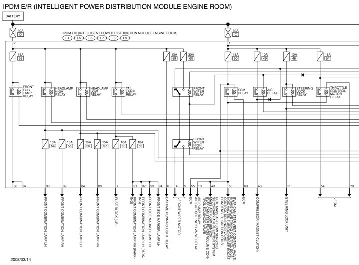
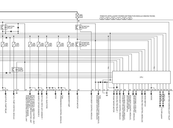
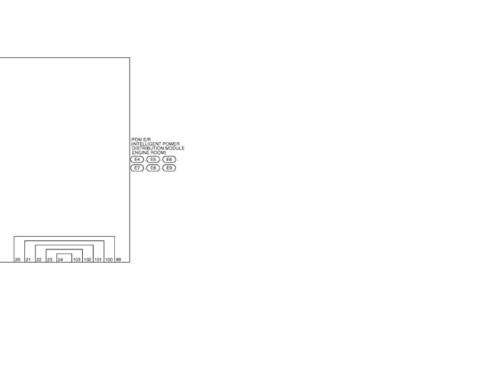
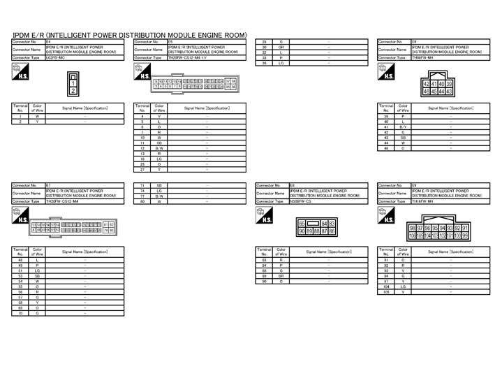
Fail-safe
CAN COMMUNICATION CONTROLWhen CAN communication with ECM and BCM is impossible, IPDM E/R performs fail-safe control. After CAN communication recovers normally, it also returns to normal control.
 If No CAN Communication Is Available With ECM
| Control part | Fail-safe operation |
| Cooling fan |
|
| A/C compressor | A/C relay OFF |
If No CAN Communication Is Available With BCM| Control part | Fail-safe operation |
| Headlamp |
|
|
|
| Front wiper |
|
| Horn | Horn OFF |
| Ignition relay | The status just before activation of fail-safe is maintained. |
| Starter motor | Starter control relay OFF |
| Steering lock unit | Steering lock relay OFF |
IGNITION RELAY MALFUNCTION DETECTION FUNCTION- IPDM E/R monitors the voltage at the contact circuit and excitation coil circuit of the ignition relay inside it.
- IPDM E/R judges the ignition relay error if the voltage differs between the contact circuit and the excitation coil circuit.
- If the ignition relay cannot turn OFF due to contact seizure, it activates the tail lamp relay and daytime running light relay* for 10 minutes to alert the user to the ignition relay malfunction when the ignition switch is turned OFF.
|
Voltage judgment |
IPDM E/R judgment |
Operation |
|
|
Ignition relay contact side |
Ignition relay excitation coil side |
||
|
ON |
ON |
Ignition relay ON normal |
— |
|
OFF |
OFF |
Ignition relay OFF normal |
— |
|
ON |
OFF |
Ignition relay ON stuck |
|
|
OFF |
ON |
Ignition relay OFF stuck |
Detects DTC “B2099: IGN RELAY OFF” |
FRONT WIPER CONTROLIPDM E/R detects front wiper stop position by a front wiper stop position signal.
When a front wiper stop position signal is in the conditions listed below, IPDM E/R stops power supply to wiper after repeating a front wiper 10 seconds activation and 20 seconds stop five times.
| Ignition switch | Front wiper switch | Front wiper stop position signal |
| ON | OFF | The front wiper stop position signal (stop position) cannot be input for 10 seconds. |
| ON | The front wiper stop position signal does not change for 10 seconds. |
NOTE:
This operation status can be confirmed on the IPDM E/R “Data Monitor” that displays “BLOCK” for the item “WIP PROT” while the wiper is stopped. STARTER MOTOR PROTECTION FUNCTIONIPDM E/R turns OFF the starter control relay to protect the starter motor when the starter control relay remains active for 90 seconds.
DTC Index
NOTE:
- The details of time display are as follows.
- CRNT: A malfunction is detected now.
- PAST: A malfunction was detected in the past.
- IGN counter is displayed on FFD (Freeze Frame data).
- The number is 0 when is detected now.
- The number increases like 1 → 2 ··· 38 → 39 after returning to the normal condition whenever IGN OFF → ON.
- The number is fixed to 39 until the self-diagnosis results are erased if it is over 39.
| CONSULT display | Fail-safe | Refer to |
| No DTC is detected. further testing may be required. | — | — |
| U1000: CAN COMM CIRCUIT | × | Description |
| B2098: IGN RELAY ON | × | Description |
| B2099: IGN RELAY OFF | — | Description |
| B2108: STRG LCK RELAY ON | — | Description |
| B2109: STRG LCK RELAY OFF | — | Description |
| B210A: STRG LCK STATE SW | — | Description |
| B210B: START CONT RLY ON | — | Description |
| B210C: START CONT RLY OFF | — | Description |
| B210D: STARTER RELAY ON | — | Description |
| B210E: STARTER RELAY OFF | — | Description |
| B210F: INTRLCK/PNP SW ON | — | Description |
| B2110: INTRLCK/PNP SW OFF | — | Description |