FUEL TANK
Exploded View
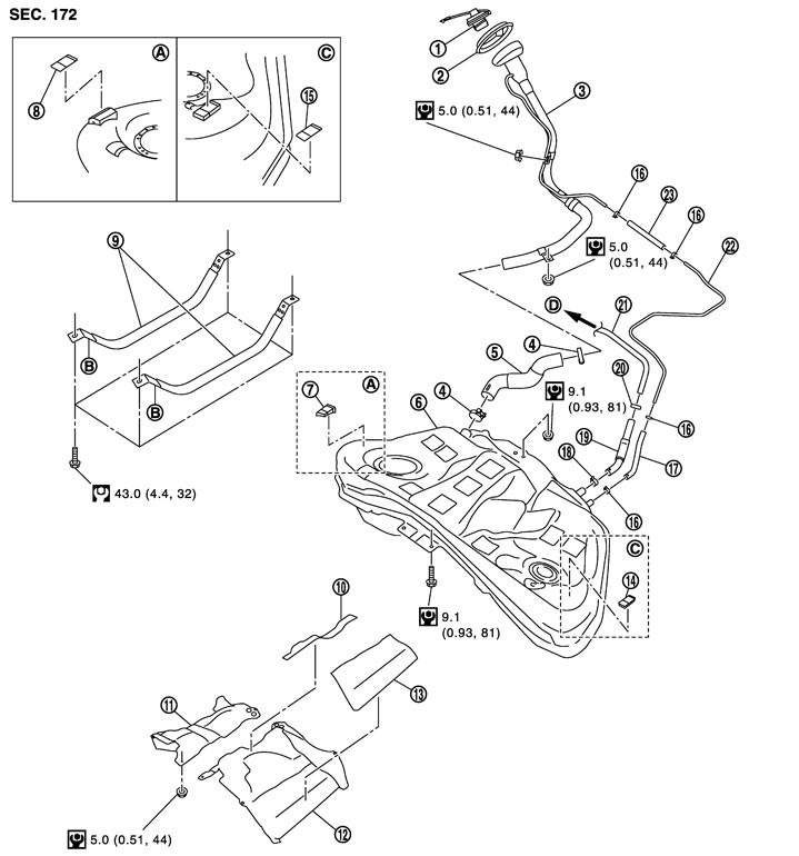
|
1. |
Fuel filler cap |
2. |
Grommet |
3. |
Fuel filler tube |
|
4. |
Clamp |
5. |
Fuel filler hose |
6. |
Fuel tank |
|
7. |
Fuel tank shim assembly |
8. |
Fuel tank shim |
9. |
Fuel tank mounting band |
|
10. |
Insulator (RH) |
11. |
Fuel tank protector (RH) |
12. |
Fuel tank protector (LH) |
|
13. |
Insulator (LH) |
14. |
Fuel tank shim assembly |
15. |
Fuel tank shim |
|
16. |
Clamp |
17. |
EVAP hose |
18. |
Clamp |
|
19. |
Vent hose |
20. |
Clamp |
21. |
Vent tube |
|
22. |
EVAP tube |
23. |
EVAP hose |
|
|
|
A. |
Right side |
B. |
Front mark |
C. |
Left side |
|
D. |
To EVAP tube |
|
|
|
|
|
Refer to Components for symbols in the figure. |
|||||
Removal and Installation
■ WARNING ■
Be sure to read “General Precautions” when working on the fuel system. Refer to General Precautions (GT-R certified NISSAN dealer).
 REMOVAL
- Drain fuel from fuel tank if necessary. Refer to Removal and Installation (GT-R certified NISSAN dealer).
- Perform work on level place.
- 1.Perform steps 2 to 7 of “REMOVAL” in “ FUEL LEVEL SENSOR UNIT, FUEL FILTER AND FUEL PUMP ASSEMBLY” on main and sub fuel level sensor units. Refer to Exploded View (GT-R certified NISSAN dealer).
- 2.Remove exhaust sub muffler and main muffler assembly. Refer to Exploded View.
- 3.Separate main propeller shaft and front propeller shaft. Refer to Exploded View (GT-R certified NISSAN dealer) and Exploded View (GT-R certified NISSAN dealer).
- 4.Remove transmission and rear suspension member assembly. Refer to Exploded View.
NOTE:
For this service, drive shaft, transmission, and rear suspension member are required not to be separate one another during removal.- 5.Disconnect EVAP hose (1), vent hose (2), and fuel filler hose (3) at fuel tank side.
- To disconnect quick connector, refer to Removal and Installation (GT-R certified NISSAN dealer).
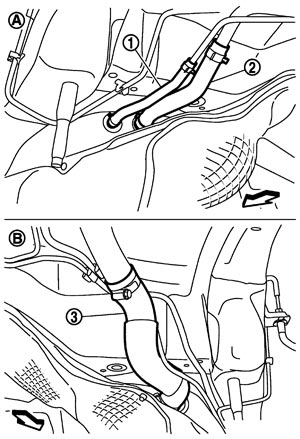
| A | : Vehicle left side |
| B | : Vehicle right side |
 | : Vehicle front |
- 6.Remove fuel tank protector.
- 7.Support the lower part of fuel tank (1) using transmission jack (A).
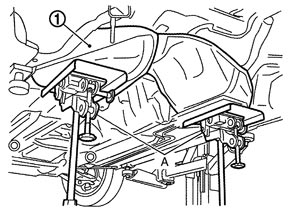
■ CAUTION ■
To secure the support, place wooden blocks or something at the position where fuel tank mounting bands never engage.- 8.Remove fuel tank mounting bands.
- 9.Remove fuel tank mounting bolts and nuts.
- 10.Supporting fuel tank with hands, descend transmission jack carefully, and remove fuel tank.
- Check that all connection points are disconnected.
- Check that there is no interference with vehicle.
■ CAUTION ■
- 11.Remove fuel filler tube if necessary.
INSTALLATIONNote the following, and install in the reverse order of removal.
- Insert hose to the length specified below and fix it by hose clamp.
Fuel filler hose : 35 mm (1.38 in) The other hoses : 25 mm (0.98 in) - Check that hose clamp is not placed on swelled area of fuel tube.
- Tighten the clamp band with the top mark (A) until the mark is on the bolt head flange.
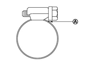
- To connect quick connector, refer to Removal and Installation (GT-R certified NISSAN dealer).
Inspection
INSPECTION AFTER REMOVAL- Check that insulator on the top surface of fuel tank protector (LH) has no peeling or displacement.
- If insulator has a peeling or displacement, replace insulator, referring to the figure.
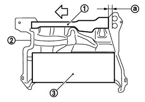
1 : Insulator (RH) 2 : Fuel tank protector (LH) 3 : Insulator (LH) a : 20 mm (0.79 in) : Vehicle front - Check that there is no malfunction on the baffle plate in the fuel tank.
INSPECTION AFTER INSTALLATIONUse the following procedure to check for fuel leakage.
- 1.Turn ignition switch “ON” (with engine stopped), and check connections for leakage by applying fuel pressure to fuel piping.
- 2.Start engine and rev it up and check there are no fuel leakage at the fuel system tube and hose connections.
- After removing/installing rear suspension assembly, check and adjust the wheel alignment. Refer to Inspection.