INTERIOR ROOM LAMP BATTERY SAVER SYSTEM
System Diagram
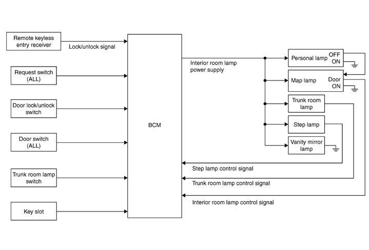
System Description
 OUTLINE
- Interior room lamp battery saver is controlled by BCM.
- BCM turns applicable lamps OFF depending on the vehicle condition. This function prevents the battery from over-discharging if the driver neglect turning OFF the any lamps.
 Applicable lamps
- Map lamp
- Step lamp
- Trunk room lamp
- Vanity mirror lamp
INTERIOR ROOM LAMP BATTERY SAVER FUNCTION- When the ignition switch is turned OFF, BCM operates the timer for a period of time to cut the interior room lamp power supply.
- BCM restart the timer when any of the following signals changes while operating the timer.
- Ignition switch status
- Door switch signal (ALL)
- Door lock/unlock signal (remote keyless entry receiver, each request switch, door lock and unlock switch)
- Trunk loom lamp switch signal
- Key switch signal (key slot)
- BCM provides the interior room lamp power supply continuously when the ignition switch position is other than OFF.
NOTE:
Each function of interior room lamp battery saver can be set by CONSULT-III. Refer to CONSULT-III Function (BCM - BATTERY SAVER).
Component Parts Location
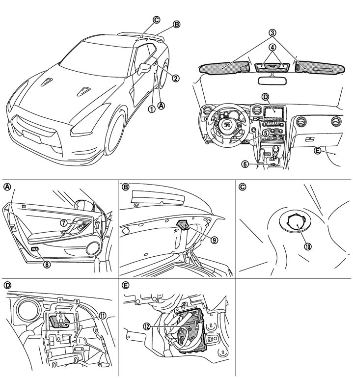
|
1. |
Door switch |
2. |
Request switch |
3. |
Vanity mirror lamp |
|
4. |
Map lamp |
5. |
Key slot |
6. |
Push-button ignition switch |
|
7. |
Door lock and unlock switch |
8. |
Step lamp |
9. |
Trunk room lamp switch |
|
10. |
Trunk room lamp |
11. |
Remote keyless entry receiver |
12. |
BCM |
|
A. |
Front door |
B. |
Trunk lid lock assembly |
C. |
Trunk room upward |
|
D. |
Behind the display |
E. |
Dash side lower (passenger side) |
|
|
Component Description
|
Part |
Description |
|
|
BCM |
Operates the interior room lamp battery saver depending on the vehicle condition to cut the interior room lamp power supply. |
|
|
Transmits the lock/unlock signal to BCM. |
|
|
Inputs a switch signal to BCM. |
|
|
Key slot |
Input the Intelligent key in status to BCM. |
|