ILLUMINATION CONTROL SYSTEM
System Diagram
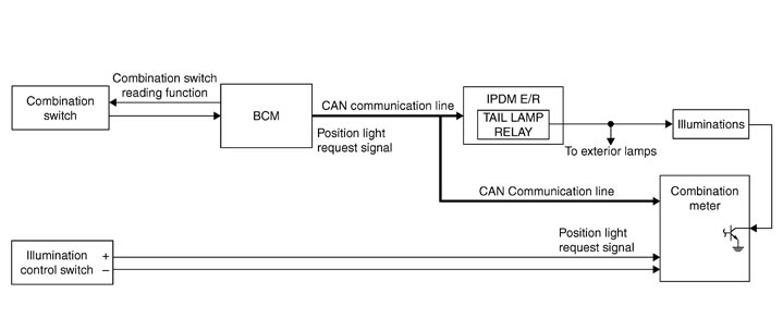
System Description
 OUTLINE
Each illumination lamp is controlled by each function of BCM, IPDM E/R and combination meter.
Control by BCM
- Combination switch reading function
- Headlamp control function
Control by IPDM E/R
- Relay control function
Control by combination meter
- Meter illumination control function (Refer to System Diagram.)
ILLUMINATION CONTROL- BCM detects the combination switch condition by the combination switch reading function.
- BCM transmits position light request signal to IPDM E/R and combination meter according to tail lamp ON condition.
- Lighting switch 1ST
- Lighting switch 2ND
- IPDM E/R turns the integrated tail lamp relay ON according to position light request signal. It provides the power supply to each illumination lamp.
- Combination meter enters in the nighttime mode according to position light request signal. Under the nighttime mode the combination meter controls the illuminance by controlling the each illumination lamp (ground side).
Tail lamp ON condition
Component Parts Location
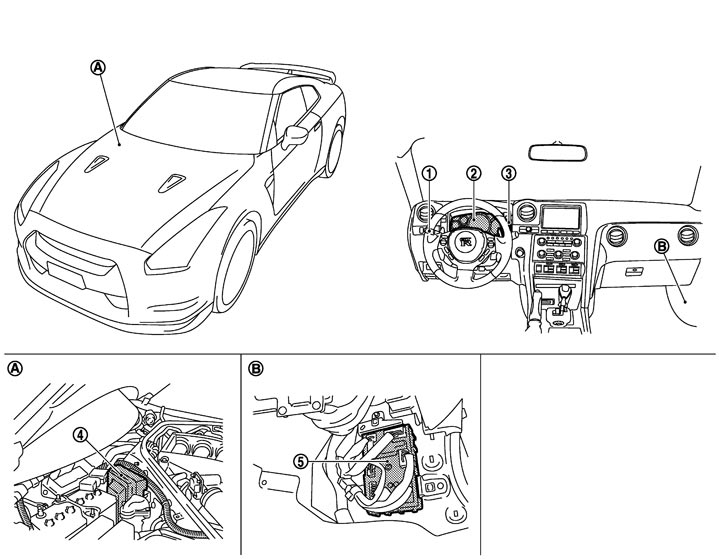
|
1. |
Combination switch |
2. |
Illumination control switch |
3. |
Combination meter |
|
4. |
BCM |
5. |
IPDM E/R |
|
|
|
A |
Dash side lower (passenger side) |
B. |
Engine room dash panel (RH) |
|
|
Component Description
|
Part |
Description |
|
|
BCM |
|
|
|
IPDM E/R |
Controls the integrated relay according to the request from BCM (with CAN communication). |
|
|
Combination meter |
|
|
|
Combination switch (Lighting and turn signal switch) |
Refer to System Diagram. |
|