VDC
VDC/TCS/ABS
System Diagram
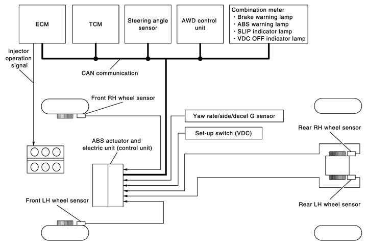
System Description
- In addition to TCS/ABS functions, Vehicle Dynamics Control (VDC) system controls brake application to four wheels and engine output to improve the stability of the vehicle, judging driving conditions (under/over steering) from the steering angle and brake application data detected by the sensors (steering angle and pressure) and from data by the sensors (yaw rate/side/decel G and wheel speed).
- During VDC operation, it informs driver of system operation by blinking the SLIP indicator lamp.
- Electrical system diagnosis by CONSULT-III is available.
- Both “VDC” and “VDC-R” are used in this manual. These indicate the same system.
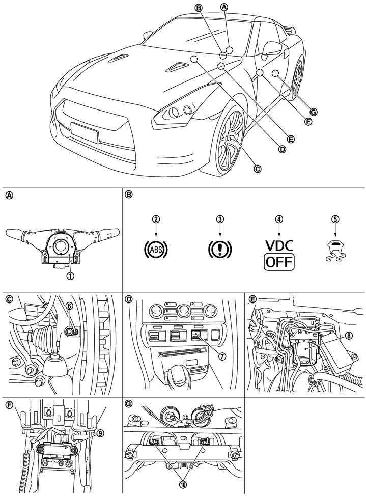
Component Parts Location
|
1. |
Steering angle sensor |
2. |
ABS warning lamp |
3. |
Brake warning lamp |
|
4. |
VDC OFF indicator lamp |
5. |
SLIP indicator lamp |
6. |
Front wheel sensor |
|
7. |
Set-up switch (VDC) |
8. |
ABS actuator and electric unit (control unit) |
9. |
Yaw rate/side/decel G sensor |
|
10. |
Rear wheel sensor |
|
|
|
|
|
A. |
Back of spiral cable assembly |
B. |
Combination meter |
C. |
Steering knuckle |
|
D. |
Instrument center panel |
E. |
Inside brake master cylinder cover |
F. |
Under rear console assembly |
|
G. |
Rear final drive assembly |
|
|
|
|