ABS ACTUATOR AND ELECTRIC UNIT (CONTROL UNIT)
VDC/TCS/ABS
Reference Value
 VALUES ON THE DIAGNOSIS TOOL
■ CAUTION ■
The display shows the control unit calculation data, so a normal value might be displayed even in the event the output circuit (harness) is open or short-circuited.
|
Monitor item |
Display content |
Data monitor |
Condition |
Reference value in normal operation |
| FR LH SENSOR | Wheel speed | Vehicle stopped | 0 [km/h (MPH)] |
| Vehicle running (Note 1) | Nearly matches the speedometer display (± 10% or less) | ||
| FR RH SENSOR | Wheel speed | Vehicle stopped | 0 [km/h (MPH)] |
| Vehicle running (Note 1) | Nearly matches the speedometer display (± 10% or less) | ||
| RR LH SENSOR | Wheel speed | Vehicle stopped | 0 [km/h (MPH)] |
| Vehicle running (Note 1) | Nearly matches the speedometer display (± 10% or less) | ||
| RR RH SENSOR | Wheel speed | Vehicle stopped | 0 [km/h (MPH)] |
| Vehicle running (Note 1) | Nearly matches the speedometer display (± 10% or less) | ||
| STOP LAMP SW | Stop lamp switch signal status | When brake pedal is depressed | On |
| When brake pedal is not depressed | Off | ||
| BATTERY VOLT | Battery voltage supplied to the ABS actuator and electric unit (control unit) | Ignition switch ON | 10 – 16 V |
| OFF SW | Set-up switch (VDC) On/Off states | When the switch is not operated | Off |
| When the switch is pushed down for 1 second or more | On | ||
| GEAR | Gear position | Vehicle running | 1 – 6 |
| SLCT LVR POSI | Shift lever position | P position R position N position D position | P R N D |
| DECEL G-SEN | Decel G detected by yaw rate/side/decel G sensor | Vehicle stopped | Approx. 0 G |
| During acceleration | Positive value | ||
| During deceleration | Negative value | ||
| YAW RATE SEN | Yaw rate detected by yaw rate/side/decel G sensor | Vehicle stopped | Approx. 0 d/s |
| Vehicle turning right | Negative value | ||
| Vehicle turning left | Positive value | ||
| FR RH IN SOL | Operation status of each solenoid valve | Actuator (solenoid valve) is active (“ACTIVE TEST” with CONSULT-III) | On |
| When the actuator (solenoid valve) is not active and actuator relay is active (ignition switch ON) | Off | ||
| FR RH OUT SOL | Operation status of each solenoid valve | Actuator (solenoid valve) is active (“ACTIVE TEST” with CONSULT-III) | On |
| When the actuator (solenoid valve) is not active and actuator relay is active (ignition switch ON) | Off | ||
| FR LH IN SOL | Operation status of each solenoid valve | Actuator (solenoid valve) is active (“ACTIVE TEST” with CONSULT-III) | On |
| When the actuator (solenoid valve) is not active and actuator relay is active (ignition switch ON) | Off | ||
| FR LH OUT SOL | Operation status of each solenoid valve | Actuator (solenoid valve) is active (“ACTIVE TEST” with CONSULT-III) | On |
| When the actuator (solenoid valve) is not active and actuator relay is active (ignition switch ON) | Off | ||
| RR RH IN SOL | Operation status of each solenoid valve | Actuator (solenoid valve) is active (“ACTIVE TEST” with CONSULT-III) | On |
| When the actuator (solenoid valve) is not active and actuator relay is active (ignition switch ON) | Off | ||
| RR RH OUT SOL | Operation status of each solenoid valve | Actuator (solenoid valve) is active (“ACTIVE TEST” with CONSULT-III) | On |
| When the actuator (solenoid valve) is not active and actuator relay is active (ignition switch ON) | Off | ||
| RR LH IN SOL | Operation status of each solenoid valve | Actuator (solenoid valve) is active (“ACTIVE TEST” with CONSULT-III) | On |
| When the actuator (solenoid valve) is not active and actuator relay is active (ignition switch ON) | Off | ||
| RR LH OUT SOL | Operation status of each solenoid valve | Actuator (solenoid valve) is active (“ACTIVE TEST” with CONSULT-III) | On |
| When the actuator (solenoid valve) is not active and actuator relay is active (ignition switch ON) | Off | ||
| MOTOR RELAY | Motor and motor relay operation | When the motor relay and motor are operating | On |
| When the motor relay and motor are not operating | Off | ||
| ACTUATOR RLY (Note 2) | Actuator relay operation | When the actuator relay is operating | On |
| When the actuator relay is not operating | Off | ||
| ABS WARN LAMP | ABS warning lamp (Note 3) | When ABS warning lamp is ON | On |
| When ABS warning lamp is OFF | Off | ||
| OFF LAMP | VDC OFF indicator lamp (Note 3) | When VDC OFF indicator lamp is ON | On |
| When VDC OFF indicator lamp is OFF | Off | ||
| SLIP LAMP | SLIP indicator lamp (Note 3) | When SLIP indicator lamp is ON | On |
| When SLIP indicator lamp is OFF | Off | ||
| ACCEL POS SIG | Throttle actuator opening/closing is displayed (linked with accelerator pedal) | Accelerator pedal not depressed (ignition switch is ON) | 0% |
| Depress accelerator pedal (ignition switch is ON) | 0 - 100% | ||
| SIDE G-SENSOR | Transverse G detected by yaw rate/side/decel G sensor | Vehicle stopped | Approx. 0 m/s2 |
| Vehicle turning right | Negative value | ||
| Vehicle turning left | Positive value | ||
| STR ANGLE SIG | Steering angle detected by steering angle sensor | Driving straight | ±2.5° |
| Turn 90 degrees to left | Approx. +90° | ||
| Turn 90 degrees to right | Approx. –90° | ||
| ENGINE RPM | With engine running | With engine stopped | 0 rpm |
| Engine running | Almost in accordance with tachometer display | ||
| PRESS SENSOR | Brake fluid pressure detected by pressure sensor | With ignition switch turned ON and brake pedal released | Approx. 0 bar |
| With ignition switch turned ON and brake pedal depressed | Approx. 0 to 300 bar | ||
| CV1 (Note 2) | VDC switch-over valve | When actuator (switch-over valve) is active (“ACTIVE TEST” with CONSULT-III) | On |
| When actuator (switch-over valve) is not active and actuator relay is active (ignition switch ON) | Off | ||
| CV2 (Note 2) | VDC switch-over valve | When actuator (switch-over valve) is active (“ACTIVE TEST” with CONSULT-III) | On |
| When actuator (switch-over valve) is not active and actuator relay is active (ignition switch ON) | Off | ||
| SV1 (Note 2) | VDC switch-over valve | When actuator (switch-over valve) is active (“ACTIVE TEST” with CONSULT-III) | On |
| When actuator (switch-over valve) is not active and actuator relay is active (ignition switch ON) | Off | ||
| SV2 (Note 2) | VDC switch-over valve | When actuator (switch-over valve) is active (“ACTIVE TEST” with CONSULT-III) | On |
| When actuator (switch-over valve) is not active and actuator relay is active (ignition switch ON) | Off | ||
| V/R OUTPUT (Note 2) | Solenoid valve relay activated | When the solenoid valve relay is active (When engine running) | On |
| When the solenoid valve relay is not active (in the fail-safe mode or engine stopped) | Off | ||
| M/R OUTPUT | Actuator motor and motor relay activated | When the actuator motor and motor relay are active (“ACTIVE TEST” with CONSULT-III) | On |
| When the actuator motor and motor relay are inactive | Off | ||
| EBD SIGNAL | EBD operation | EBD is active | On |
| EBD is inactive | Off | ||
| ABS SIGNAL | ABS operation | ABS is active | On |
| ABS is inactive | Off | ||
| TCS SIGNAL | TCS operation | TCS is active | On |
| TCS is inactive | Off | ||
| VDC SIGNAL | VDC operation | VDC is active | On |
| VDC is inactive | Off | ||
| EBD FAIL SIG | EBD fail-safe signal | In EBD fail-safe | On |
| EBD is normal | Off | ||
| ABS FAIL SIG | ABS fail-safe signal | In ABS fail-safe | On |
| ABS is normal | Off | ||
| TCS FAIL SIG | TCS fail-safe signal | In TCS fail-safe | On |
| TCS is normal | Off | ||
| VDC FAIL SIG | VDC fail-safe signal | In VDC fail-safe | On |
| VDC is normal | Off | ||
| CRANKING SIG | Crank operation | Crank is active | On |
| Crank is inactive | Off | ||
| FLUID LEV SW | Brake fluid level switch signal status | When brake fluid level switch ON | On |
| When brake fluid level switch OFF | Off |
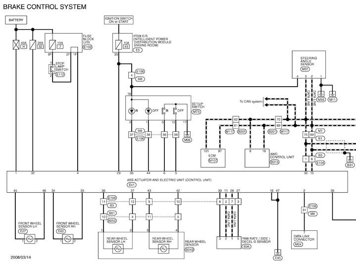
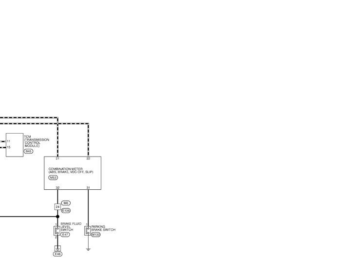
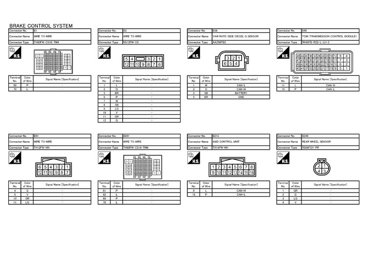
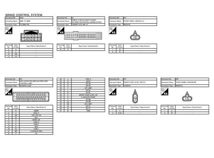
Wiring Diagram - BRAKE CONTROL SYSTEM -
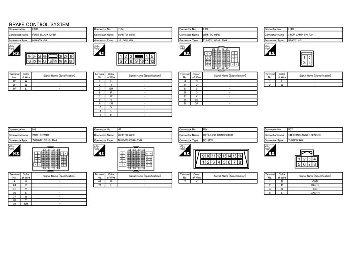
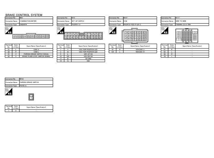
Fail-Safe
ABS, EBD SYSTEMIf ABS malfunctions electrically, ABS warning lamp, VDC OFF indicator lamp, and SLIP indicator lamp will turn on. If EBD malfunctions electrically, brake warning lamp, ABS warning lamp, VDC OFF indicator lamp, and SLIP indicator lamp will turn on. Simultaneously, the VDC/TCS/ABS changes to one of the following conditions of the fail-safe function.
- For malfunction of ABS, only the EBD is activated and the condition of vehicle is the same condition of vehicles without TCS/ABS system.NOTE:ABS self-diagnosis sound may be heard. That is a normal condition because a self-diagnosis for “Ignition switch ON” and “The first starting” are being performed.
- When EBD and ABS is inoperative because of a malfunction, and the condition of vehicle becomes the same as the condition of vehicles without TCS/ABS, EBD system.
VDC/TCS, Hill start assistIf VDC/TCS/ABS and hill start assist system malfunction electrically, VDC OFF indicator lamp, and SLIP indicator lamp are turned on, and the condition of vehicle is the same as the condition of vehicles without VDC/TCS control and hill start assist system.
■ CAUTION ■
If the Fail-Safe function is activated, then perform self-diagnosis for VDC/TCS/ABS control system.