ALTERNATOR
Exploded View
 REMOVAL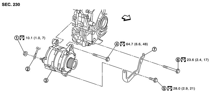
|
1. |
“B” terminal nut |
2. |
“B” terminal harness |
3. |
Alternator |
|
4. |
Alternator mounting upper bolt |
5. |
Alternator mounting lower bolt |
6. |
Alternator stay mounting bolt |
|
7. |
Alternator stay |
|
|
|
|
 : Engine front : Engine front |
|||||
|
Refer to Components for symbols in the figure. |
|||||
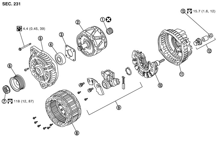
DISASSEMBLYType: A002TX0091
|
1. |
Rear bearing |
2. |
Rotor assembly |
3. |
Retainer |
|
4. |
Front bearing |
5. |
Front bracket assembly |
6. |
Pulley |
|
7. |
Pulley nut |
8. |
Stator assembly |
9. |
IC voltage regulator assembly |
|
10. |
Diode assembly |
11. |
Rear bracket assembly |
12. |
Terminal set |
|
13. |
“B” terminal nut |
|
|
|
|
|
Refer to Components for symbols in the figure. |
|
|
|||
Removal and Installation
REMOVAL- 1.Disconnect the battery cable from the negative terminal.
- 2.Remove drive belt. Refer to Removal and Installation (GT-R certified NISSAN dealer).
- 3.Remove drive belt auto tensioner and idler pulley bracket side. Refer to Exploded View.
- 4.Remove engine front undercover, using power tools.
- 5.Remove alternator mounting upper bolt.
- 6.Disconnect oil pressure switch connector.
- 7.Pull up alternator, and then disconnect alternator connector (1).
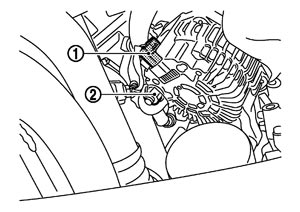
- 8.Remove “B” terminal nut (2).
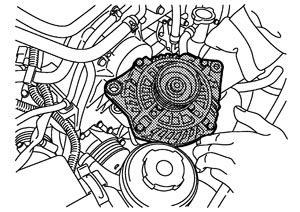
- 9.Remove alternator assembly upward from the vehicle.
 INSTALLATION
Install in the reverse order of removal.
■ CAUTION ■
Be sure to tighten “B” terminal nut carefully.Install alternator, and check tension of belt. Refer to Checking.
Inspection
ALTERNATOR PULLEY INSPECTIONPerform the following.
- Make sure that alternator pulley does not rattle.
- Make sure that alternator pulley nut is tight. Refer to Exploded View.