TCS
VDC/TCS/ABS
System Diagram
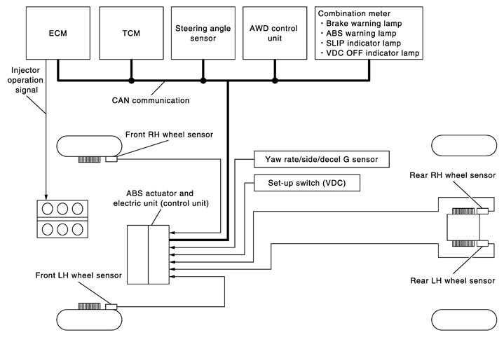
System Description
- TCS controls electronically controls engine torque, brake fluid pressure, and A/T gear position to ensure the optimum slippage ratio at drive wheels by computing wheel speed signals from 4 wheel sensors. When the ABS actuator and electric unit (control unit) detects a drive wheel spin at drive wheels (rear wheels), it compares wheel speed signals from all 4 wheels. At this time, LH and RH rear brake fluid pressure is controlled, while fuel is cut to engine and throttle valve being is adjusted to reduce engine torque by the control unit. Further more, throttle position is controlled to ensure the optimum engine torque.
- During TCS operation, TCS informs driver of system operation by blinking the SLIP indicator lamp.
- Electrical system diagnosis by CONSULT-III is available.
Component Parts Location
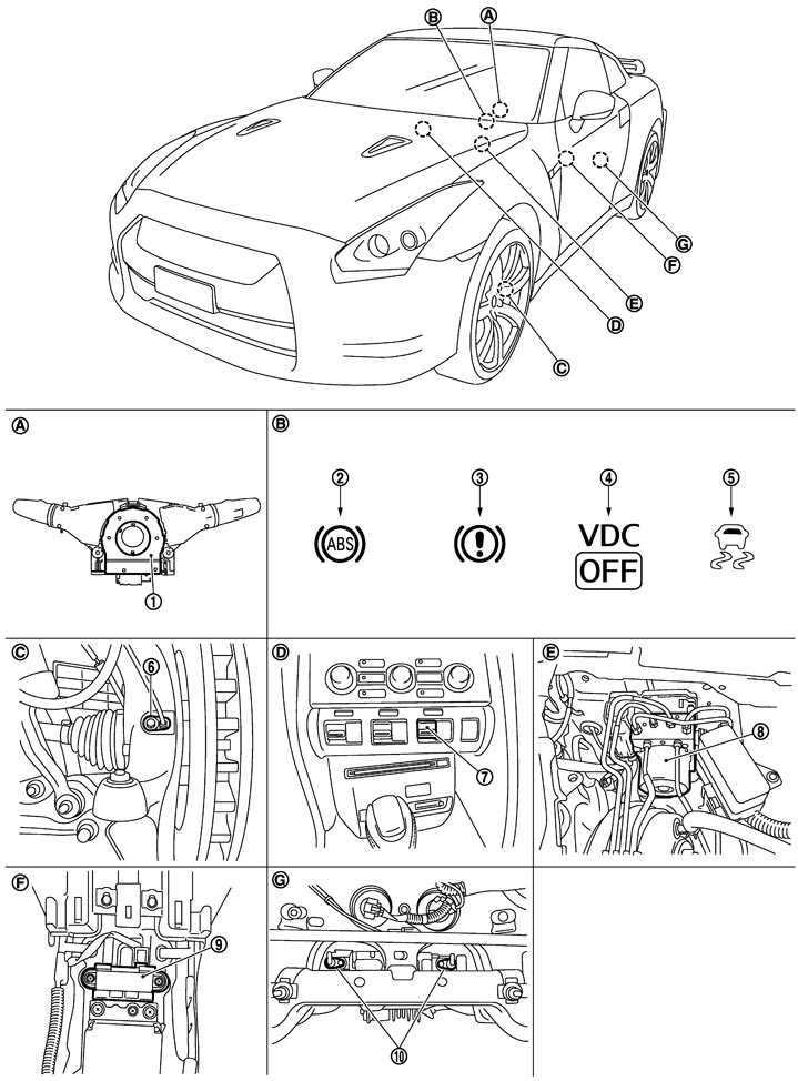
|
1. |
Steering angle sensor |
2. |
ABS warning lamp |
3. |
Brake warning lamp |
|
4. |
VDC OFF indicator lamp |
5. |
SLIP indicator lamp |
6. |
Front wheel sensor |
|
7. |
Set-up switch (VDC) |
8. |
ABS actuator and electric unit (control unit) |
9. |
Yaw rate/side/decel G sensor |
|
10. |
Rear wheel sensor |
|
|
|
|
|
A. |
Back of spiral cable assembly |
B. |
Combination meter |
C. |
Steering knuckle |
|
D. |
Instrument center panel |
E. |
Inside brake master cylinder cover |
F. |
Under rear console assembly |
|
G. |
Rear final drive assembly |
|
|
|
|