ABS
VDC/TCS/ABS
System Diagram
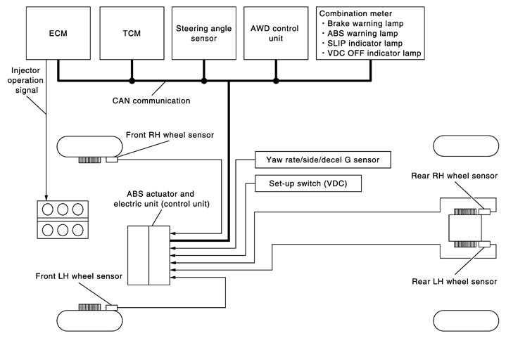
System Description
- Anti-Lock Braking System detects wheel revolution while braking, electronically controls braking force, and prevents wheel locking during sudden braking. It improves handling stability and maneuverability for avoiding obstacles.
- Electrical system diagnosis by CONSULT-III is available.
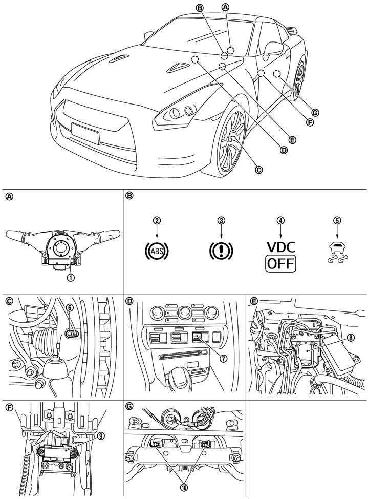
Component Parts Location
|
1. |
Steering angle sensor |
2. |
ABS warning lamp |
3. |
Brake warning lamp |
|
4. |
VDC OFF indicator lamp |
5. |
SLIP indicator lamp |
6. |
Front wheel sensor |
|
7. |
Set-up switch (VDC) |
8. |
ABS actuator and electric unit (control unit) |
9. |
Yaw rate/side/decel G sensor |
|
10. |
Rear wheel sensor |
|
|
|
|
|
A. |
Back of spiral cable assembly |
B. |
Combination meter |
C. |
Steering knuckle |
|
D. |
Instrument center panel |
E. |
Inside brake master cylinder cover |
F. |
Under rear console assembly |
|
G. |
Rear final drive assembly |
|
|
|
|