EBD
VDC/TCS/ABS
System Diagram
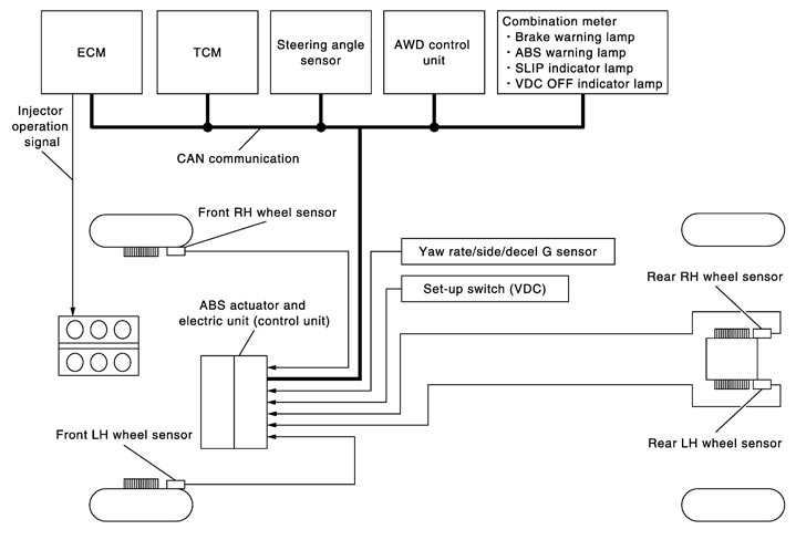
System Description
- The ABS actuator and electric unit (control unit) detects subtle slippage between the front and rear wheels during braking. Then it reduces the rear braking force (brake fluid pressure) and rear wheel slippage. Thus improving vehicle stability.
- Electrical system diagnosis by CONSULT-III is available.
Component Parts Location
|
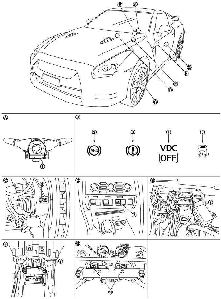
1. |
Steering angle sensor |
2. |
ABS warning lamp |
3. |
Brake warning lamp |
|
4. |
VDC OFF indicator lamp |
5. |
SLIP indicator lamp |
6. |
Front wheel sensor |
|
7. |
Set-up switch (VDC) |
8. |
ABS actuator and electric unit (control unit) |
9. |
Yaw rate/side/decel G sensor |
|
10. |
Rear wheel sensor |
|
|
|
|
|
A. |
Back of spiral cable assembly |
B. |
Combination meter |
C. |
Steering knuckle |
|
D. |
Instrument center panel |
E. |
Inside brake master cylinder cover |
F. |
Under rear console assembly |
|
G. |
Rear final drive assembly |
|
|
|
|