CAN COMMUNICATION SYSTEM
CAN FUNDAMENTAL
System Description
- CAN communication is a multiplex communication system. This enables the system to transmit and receive large quantities of data at high speed by connecting control units with two communication lines (CAN-H and CAN-L).
- Control units on the CAN network transmit signals using the CAN communication control circuit. They receive only necessary signals from other control units to operate various functions.
- CAN communication lines adopt twisted-pair line style (two lines twisted) for noise immunity.
System Diagram
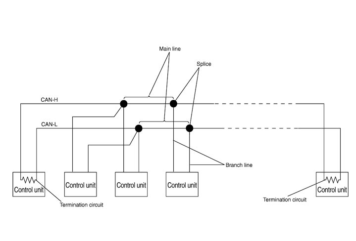
Each control unit passes an electric current to the termination circuits when transmitting CAN communication signal. The termination circuits produce an electrical potential difference between CAN-H and CAN-L. CAN communication system transmits and receives CAN communication signals by the potential difference.
| Component | Description |
| Main line | CAN communication line between splices |
| Branch line | CAN communication line between splice and a control unit |
| Splice | A point connecting a branch line with a main line |
| Termination circuit | Refer to CAN Communication Control Circuit. |
CAN Communication Control Circuit
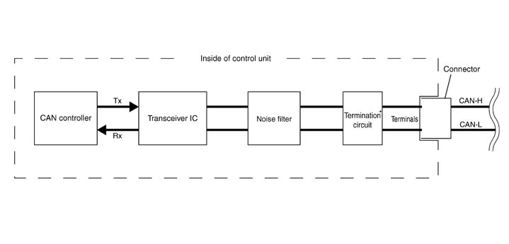
|
Component |
System description |
|
CAN controller |
It controls CAN communication signal transmission and reception, error detection, etc. |
|
Transceiver IC |
It converts digital signal into CAN communication signal, and CAN communication signal into digital signal. |
|
Noise filter |
It eliminates noise of CAN communication signal. |
|
Termination circuit* (Resistance of approx. 120 Ω) |
It produces potential difference. |